
Full-automatic grinding machine

A fully automatic grinding machine and grinding head technology, applied in grain processing and other directions, can solve the problems of inability to control the particle size, inability to control the timing of material discharge, and no particle size adjustment function, and achieve the effect of rapid drop.

Active Publication Date: 2019-08-16
黑龙江隆腾食品科技有限公司
View PDF11 Cites 7 Cited by
  • Summary
  • Abstract
  • Description
  • Claims
  • Application Information

AI Technical Summary

Problems solved by technology

[0003] In actual production, the material cannot leave the mill freely from the discharge end. The discharge end of the mill has the function of inhibiting the discharge of large particles, and the small particles can be discharged smoothly, while the large particles remain in the mill. This effect is called outlet classification; this method cannot control the timing of material discharge, and cannot control the particle size; at the same time, the existing grinder does not have the function of adjusting the particle size, making the grinding machine Single scope of application

Method used


Image

  • Full-automatic grinding machine
  • Full-automatic grinding machine
  • Full-automatic grinding machine

Examples


Embodiment approach

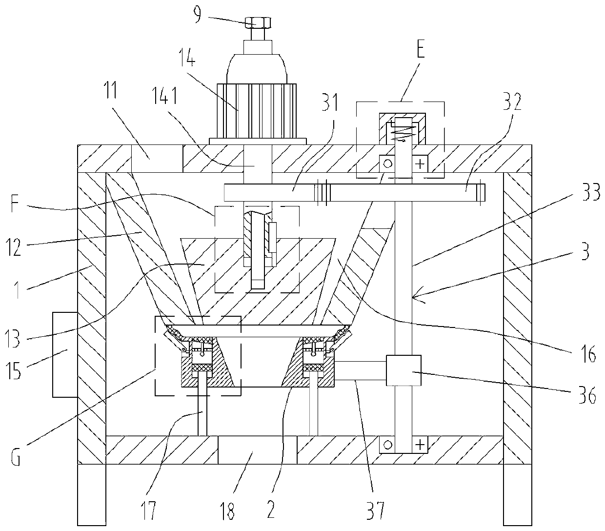
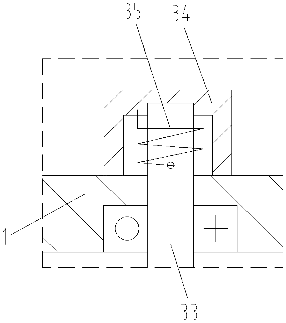
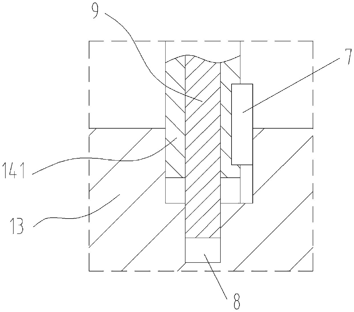
[0025] As an embodiment of the present invention, the driving device 3 includes a sector gear 31, a linkage gear 32, a screw rod 33, a cover plate 34, a rotary torsion spring 35, a slider 36 and a connecting rod 37; the middle part of the rotating shaft 141 of the motor 14 is fixed Connect the sector gear 31, one side of the sector gear 31 is provided with a linkage gear 32 that is meshed with it in a gap; the linkage gear 32 is fixedly connected to the outer ring of the screw 33, and the lower end of the screw 33 is rotationally connected with the bottom plate of the box body 1. The upper end of the screw rod 33 runs through the top plate of the box body 1 and is rotatably connected with the cover plate 34. The cover plate 34 is fixedly connected to the top of the box body 1. The cover plate 34 is provided with a rotary torsion spring 35 sleeved on the outer ring of the screw rod 33. One end of the spring 35 is fixedly connected on the cover plate 34, and the other end of the ...


PUM


Abstract

The invention relates to the technical field of grinding equipment, in particular to a full-automatic grinding machine. The full-automatic grinding machine comprises a box body, a feed port, a conicalbarrel, a grinding head, a motor, a controller, guide columns, a discharge port, a stopper and a driving device; the bottom of a top plate of the box body is fixedly connected with the conical barrel; the conical grinding head is arranged in the conical barrel; an annular grinding channel is formed between the grinding head and the conical barrel; the lower end width of the grinding channel is smaller than the upper end width; the stopper is annular corresponding to the grinding channel; the cross section of the stopper is arranged as a right trapezoid; a slope surface of the stopper is arranged on an inner ring, and a conical blanking channel is formed in the middle part; the discharge port is formed under the blanking channel; and the stopper is slidingly mounted on one set of guide columns. A rubber ring is provided; the inner ring of the rubber ring is thicker than an outer ring, and the thinner place is projected higher, so that materials dropping on the rubber ring are easy to fall; and meanwhile, a pull rod is connected to the bottom of the rubber ring, and the rubber ring is vibrated to enable the materials to quickly fall.

Description

technical field [0001] The invention relates to the technical field of grinding equipment, in particular to a fully automatic grinding machine. Background technique [0002] The pulverizer is widely used in the grinding processing of mineral products in the fields of metallurgy, building materials, chemical industry, mining and so on. According to the fineness of the ground material and the fineness of the discharged material, the mill can be divided into vertical pendulum mill, high-pressure suspension roller mill, high-pressure micro-powder mill, straight-through centrifugal mill, super-pressure trapezoidal mill There are six types of pulverizers: pulverizer, three-ring medium-speed pulverizer. [0003] In actual production, the material cannot leave the mill freely from the discharge end. The discharge end of the mill has the function of inhibiting the discharge of large particles, and the small particles can be discharged smoothly, while the large particles remain in th...

Claims


Application Information

Patent Timeline
IPC IPC(8): B02C4/10B02C4/28B02C4/30B02C4/34B02C23/02
CPCB02C4/10B02C4/28B02C4/286B02C4/30B02C4/34
Inventor 秦培马其杰
Owner 黑龙江隆腾食品科技有限公司
Learn More