Wafer cutting machine with dust removal mechanism

A cutting machine and cutting mechanism technology, applied in the direction of manufacturing tools, fine working devices, working accessories, etc., can solve the problems of affecting chip quality, easily affecting test results, maintenance, etc., and achieve the effect of avoiding flying dust

Inactive Publication Date: 2018-12-07
重庆市嘉凌新科技有限公司
View PDF9 Cites 9 Cited by
  • Summary
  • Abstract
  • Description
  • Claims
  • Application Information

AI Technical Summary

Problems solved by technology

Dust will be generated during cutting, and the cut products will directly enter the optical inspection equipment for inspection. The dust attached to the product will easily affect the inspection results and be judged as unqualified by the system. At the same time, it will affect the inspection lens. The dust will be adsorbed on the

Method used


Image

  • Wafer cutting machine with dust removal mechanism
  • Wafer cutting machine with dust removal mechanism
  • Wafer cutting machine with dust removal mechanism

Examples


Embodiment Construction

[0025] Further detailed explanation through specific implementation mode below:

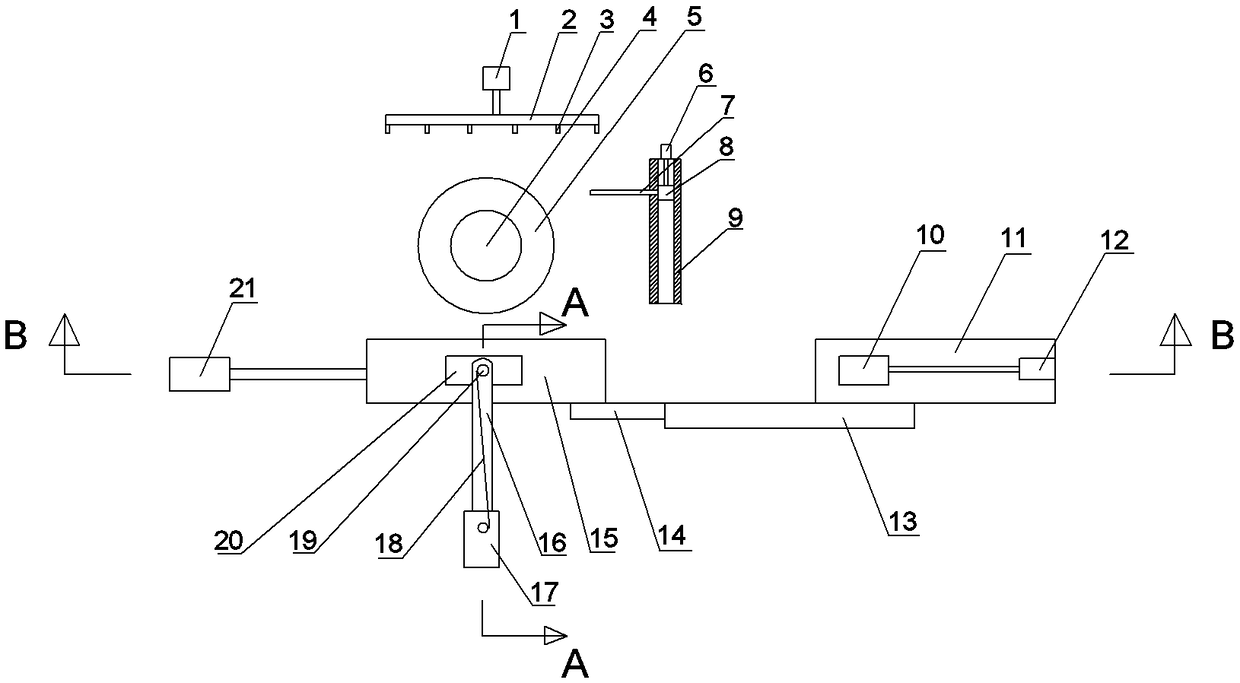
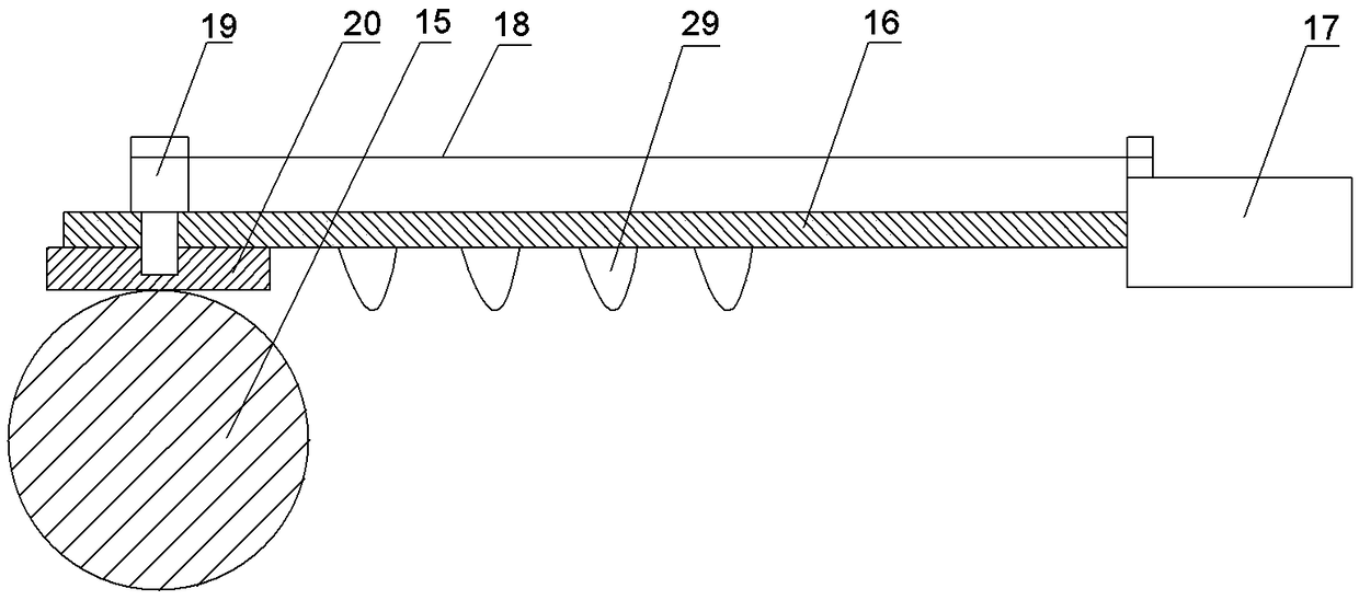
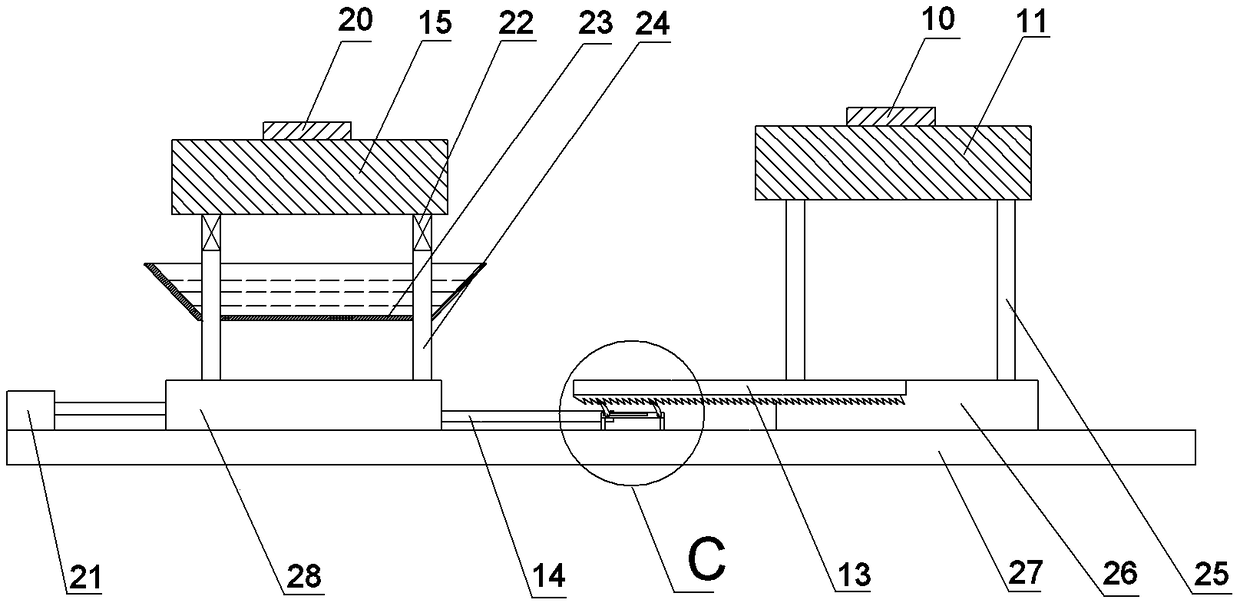
[0026] The reference signs in the drawings of the description include: blower 1, air duct 2, air nozzle 3, wafer 4, wafer placement table 5, linear motor 6, support rod 7, first hydraulic cylinder 8, slide rail 9, silk Friction layer 10, glass rod 11, third hydraulic cylinder 12, ratchet rack 13, support arm 14, rubber rod 15, connecting rod 16, second hydraulic cylinder 17, rope 18, rotating shaft 19, fur friction layer 20, cylinder 21 , shaking spring 22, dust collection tank 23, first vertical support frame 24, second vertical support frame 25, second support seat 26, base 27, first support seat 28, shaking protrusion 29, electric telescopic rod 31 , connecting plate 32, non-return ratchet 33, drive ratchet 34, transverse chute 35.

[0027] like figure 1 As shown, the chip cutting machine with a dust removal mechanism in this embodiment includes a frame on which a wafer placement table 5 is ...


PUM


Abstract

The invention belongs to the field of semiconductor wafer machining, and particularly discloses a wafer cutting machine with a dust removal mechanism. The wafer cutting machine comprises a machine frame; the machine frame is provided with a wafer placement table; a cutting mechanism is arranged on the wafer placement table; one side of the wafer placement table is provided with the dust removal mechanism; the dust removal mechanism comprises a first supporting seat and a second supporting seat which are transversely and slidably connected to the machine frame; a transverse rubber rod is connected to the first supporting seat, and a transverse glass rod is connected to the second supporting seat; the position, above the rubber rod, of the machine frame is transversely and slidably connectedwith a fur friction layer; the machine frame is provided with a fur driving mechanism used for driving the fur friction layer to transversely slide; the position, above the glass rod, of the machineframe is transversely and slidably connected with a silk friction layer attached to the top of the glass rod; and the machine frame is provided with a silk driving mechanism used for driving the silkfriction layer to transversely slide. Through the wafer cutting machine, the effect that dust is removed while a wafer is cut can be achieved, and the situation that the follow-up wafer detection result is influenced due to the fact that dust adheres to the cut wafer is avoided.

Description

technical field [0001] The invention relates to the field of semiconductor wafer processing, in particular to a chip cutting machine with a dust removal mechanism. Background technique [0002] In the electronics industry, a wafer is a collective term for thin sheets of semiconductor material used to manufacture integrated circuits or other micro-devices, also known as silicon wafers, substrates, etc. Wafers are processed into bare chips of integrated circuits, which need to go through many demanding and precise processes. In general, the process flow of wafers is generally divided into front-end process and back-end process in the industry. The front-end process mainly refers to the formation of crystals on the wafer and some technological processes adopted to realize crystal formation; the back-end process mainly refers to the process of passing the wafer with the generated circuit through a series of post-processes to process the wafer into a The process during the circ...

Claims


Application Information

Patent Timeline
IPC IPC(8): B28D5/00B28D5/04B28D7/02
CPCB28D5/0076B28D5/04
Inventor 黄晓波
Owner 重庆市嘉凌新科技有限公司
Why Eureka
Try Eureka