Recyclable agricultural mulch punching equipment

A technology for perforating equipment and mulching film, which is applied in the fields of botanical equipment and methods, plant protection cover, gardening, etc., can solve the problems of inability to automatically collect waste films, and difficulty in equidistant perforation, so as to save labor costs and ensure stability. Growth, easy to drop effect

Active Publication Date: 2020-01-07
江西璞实生态农业有限公司
View PDF5 Cites 7 Cited by
  • Summary
  • Abstract
  • Description
  • Claims
  • Application Information

AI Technical Summary

Problems solved by technology

[0005] In order to overcome the shortcomings of being difficult to equidistantly punch holes and not being able to automatically collect waste films, the technical pr

Method used


Image

  • Recyclable agricultural mulch punching equipment
  • Recyclable agricultural mulch punching equipment

Examples


Embodiment 1

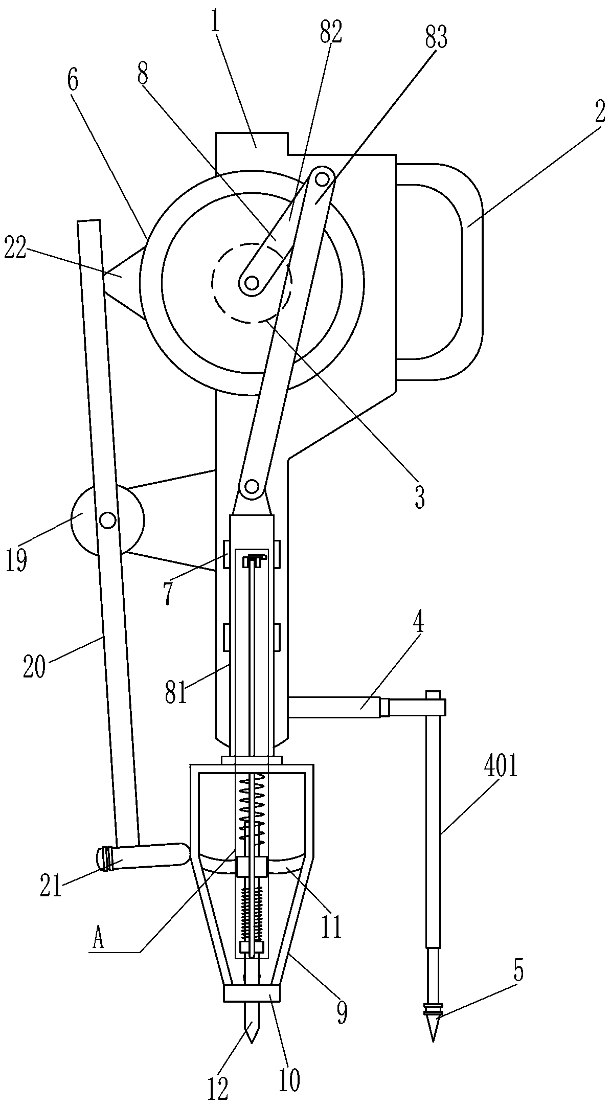
[0018] A recyclable agricultural film punching equipment, such as Figure 1-2 As shown, it includes a slide rail plate 1, a handle 2, a drive motor 3, a first telescopic rod 4, a second telescopic rod 401, a plug 5, a disc 6, a slider 7, an up and down reciprocating device 8, an installation frame 9, Cutting ring 10, guide plate 11, barb insert rod 12 and first compression spring 13, handle 2 is provided on the upper right side of slide rail plate 1, drive motor 3 is provided on the upper front side of slide rail plate 1, slide rail plate 1 The lower part of the right side is provided with the first telescopic link 4, the first telescopic link 4 right part is provided with the second telescopic link 401, the second telescopic link 401 end is provided with the plug 5, and the drive motor 3 front end output shaft is connected with the disc 6, slides The lower part of the rail plate 1 is slidably connected with sliders 7 up and down, and the front ends of the sliders 7 on both si...

Embodiment 2

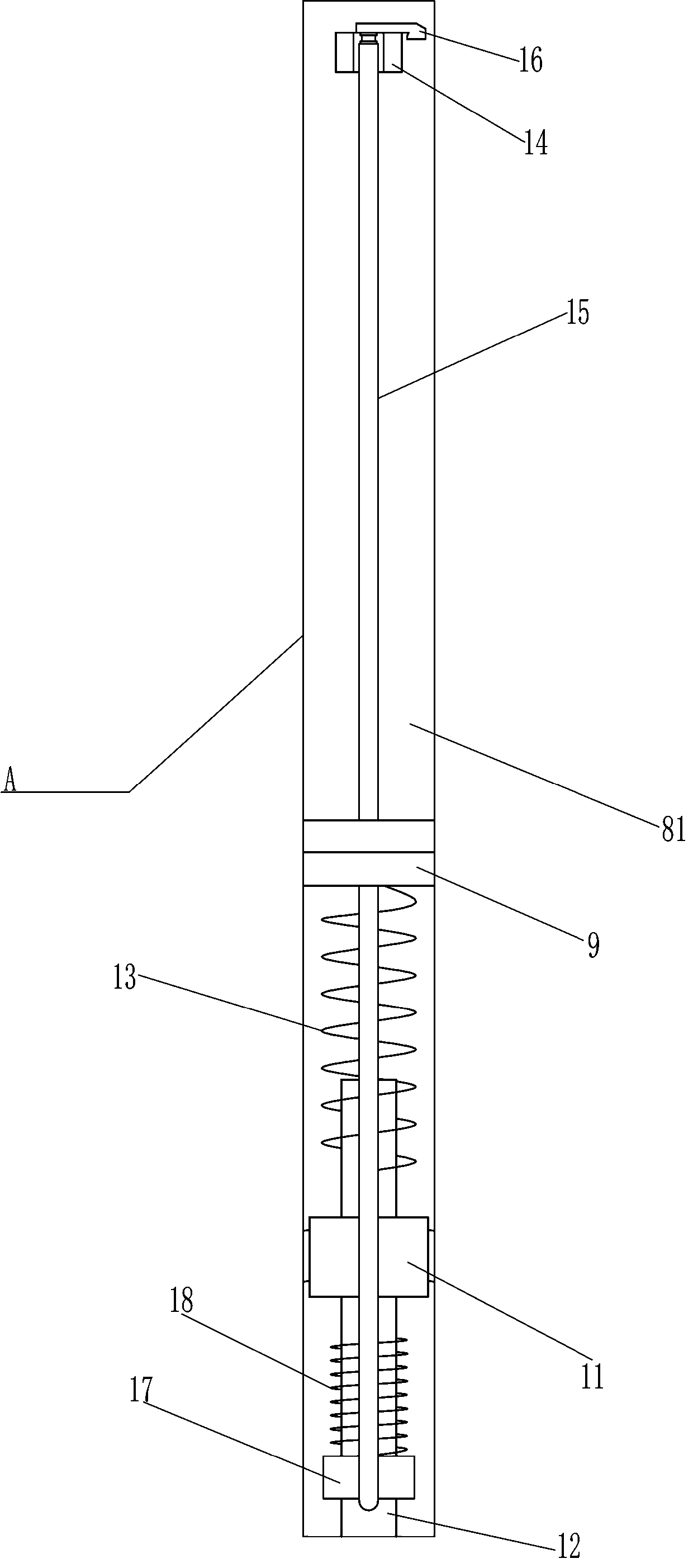
[0022] On the basis of Example 1, such as Figure 1-2 As shown, it also includes a block 14, a slide bar 15, a support plate 16, a push sleeve 17 and a second compression spring 18. The upper part of the front side of the strip plate 81 is provided with a block 14, and the block 14 is slidably connected with a sliding Rod 15, the lower part of the sliding rod 15 is slidably connected with the top of the installation frame 9, the sliding rod 15 is located at the front side of the guide plate 11, the rear side of the lower part of the sliding rod 15 is provided with a push sleeve 17, and the push sleeve 17 is slidably connected with the barbed insertion rod 12 , the top of the push sleeve 17 is connected with a second compression spring 18, the top of the second compression spring 18 is connected with the upper part of the barb insertion rod 12, the second compression spring 18 is in a compressed state, and the top of the slide bar 15 is rotatably connected with a support plate 1...

Embodiment 3

[0025] On the basis of Example 2, such as figure 1 Shown, also include supporting base 19, rotating rod 20, rubber percussion column 21 and rubber bump 22, slide rail plate 1 left side lower part is provided with supporting base 19, is connected with rotating rod 20 in the rotating type on supporting base 19, The end of the rotating rod 20 is connected with a rubber percussion post 21 , and the rear side of the disk 6 is provided with a rubber bump 22 .

[0026] When the disc 6 rotates, the disc 6 drives the rubber bump 22 to rotate, and through the cooperation of the rubber bump 22 and the rotating rod 20, the rubber knocking post 21 knocks the surface of the installation frame 9 intermittently.


PUM


Abstract

The invention relates to punching equipment, in particular to recyclable agricultural mulch punching equipment which can realize equidistant punching and automatically collect waste films. The recyclable agricultural mulch punching equipment comprises a sliding rail plate and a handle arranged on the upper portion of the right side of the sliding plate. Through equidistant punching of a thin film,convenience is brought to reasonably distributing planting density, and survival rate of plants is ensured; by recycling the thin film left after punching, stable growth of plant roots is ensured togreatest extent, convenience is brought to the plants to quickly absorb water and nutrient, growth speed is increased, and effective protection of environment is embodied; by automatically removing the round thin film, labor cost of farmers is omitted, and working efficiency is improved; the surface of a mounting frame is knocked intermittently through a rubber knocking column, so that convenienceis brought to quick falling of soil left in the mounting frame.

Description

technical field [0001] The invention relates to a punching device, in particular to a recyclable agricultural plastic film punching device. Background technique [0002] The thickness of agricultural film is only half of that of ordinary film, and the corresponding use cost is also reduced by half. At the same time, its light transmittance and thermal insulation are also better than ordinary films, and it has a significant heat preservation and moisturizing effect, so it is widely used in various kind of agricultural production. [0003] For the film laid on the soil surface, farmers often need to punch holes on the surface to facilitate the planting of crops in the soil later. The traditional punching method is generally for farmers to punch holes by hand. Although this method is convenient and fast, but due to its precision Insufficient, leading to the inability to reasonably distribute the planting density of crops, resulting in insufficient sunlight distribution of crop...

Claims


Application Information

Patent Timeline
IPC IPC(8): A01G13/02
CPCA01G13/0287
Inventor 徐涛
Owner 江西璞实生态农业有限公司
Why Eureka
Try Eureka