Mixed multistage dust collector

A dust collector and housing technology, applied in the mechanical field, can solve the problems of increasing the workload of the dehydration and defogging plate, reducing the stability of the dust collector, etc.

Active Publication Date: 2015-04-01
ZHEJIANG JIEYU ENVIRONMENTAL PROTECTION EQUIPCO
View PDF9 Cites 8 Cited by
  • Summary
  • Abstract
  • Description
  • Claims
  • Application Information

AI Technical Summary

Problems solved by technology

[0007] However, it completely relies on the dehydration and defogging plate for dehydration and defogging, which i

Method used


Image

  • Mixed multistage dust collector
  • Mixed multistage dust collector
  • Mixed multistage dust collector

Examples


Embodiment Construction

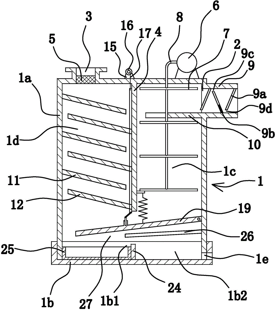
[0072] like figure 1 As shown, the hybrid multi-stage dust collector includes a housing 1 with a cavity inside. In this embodiment, the housing 1 is composed of upper and lower parts, namely: an upper housing 1a and a lower housing connected to the lower part of the upper housing 1a. Housing 1b.

[0073] The housing 1 has an inlet 2 and an outlet 3 communicating with it. The dusty air enters the housing 1 through the inlet 2, and the purified air is discharged from the outlet 3 after filtering.

[0074] A partition 4 is vertically provided in the housing 1, and the partition 4 divides the interior of the housing 1 into two adjacent cavities on the left and right: cavity one 1c and cavity two 1d. In this embodiment, both cavity one 1c and cavity two 1d are located in the upper casing 1 .

[0075] The lower parts of cavity one 1c and cavity two 1d are in communication. In this embodiment, the connection between the above two cavities is located in the lower casing 1b.

[0076...


PUM


Abstract

The invention provides a mixed multistage dust collector belonging to the technical field of mechanisms and solving the problem of complex structure of the existing dust collector. The mixed multistage dust collector comprises a shell internally provided with a cavity, wherein an inlet and an outlet which are communicated with the shell are formed in the shell; the shell is internally provided with a partition plate; the interior of the shell is partitioned by the partition plate to form two cavities, namely a cavity I and a cavity II which are adjacent left and right; the lower part of the cavity I is communicated with the lower part of the cavity II; the inlet is located in the upper part of the cavity I; the outlet is located in the top of the cavity II and is fixedly connected with a filter screen; the inlet of the cavity I is provided with a spraying mechanism capable of spraying water mist; the cavity II is internally provided with a baffling mechanism capable of baffling air flow; and a water outlet communicated with the inner cavity of the shell is also formed in the bottom of the shell. The mixed multistage dust collector is simple in structure and convenient to mount and dismount.

Description

technical field [0001] The invention belongs to the technical field of machinery, and relates to a dust collector, in particular to a hybrid multistage dust collector. Background technique [0002] During the processing of existing stone materials such as grinding and cutting and polishing of workpieces, dust is flying in the air, which seriously affects the health of workers. In order to reduce the impact of dust on workers' bodies, people invented a grinding dust removal device. [0003] For example, Chinese utility model patent (application number: 201120380957.5; authorized announcement number: CN202237691U) discloses a kind of dust collection equipment for a grinding room, which includes a dust collection room, a water storage tank, etc., and the water collection tank is located at the bottom of the dust collection room and above the water collection tank. Equipped with circulating water pump. When the vacuuming equipment is just starting to work, the sump needs to be...

Claims


Application Information

Patent Timeline
IPC IPC(8): B01D50/00
Inventor 许金生徐佳丽钱林浩查晓峰葛伟浩
Owner ZHEJIANG JIEYU ENVIRONMENTAL PROTECTION EQUIPCO
Why Eureka
Try Eureka