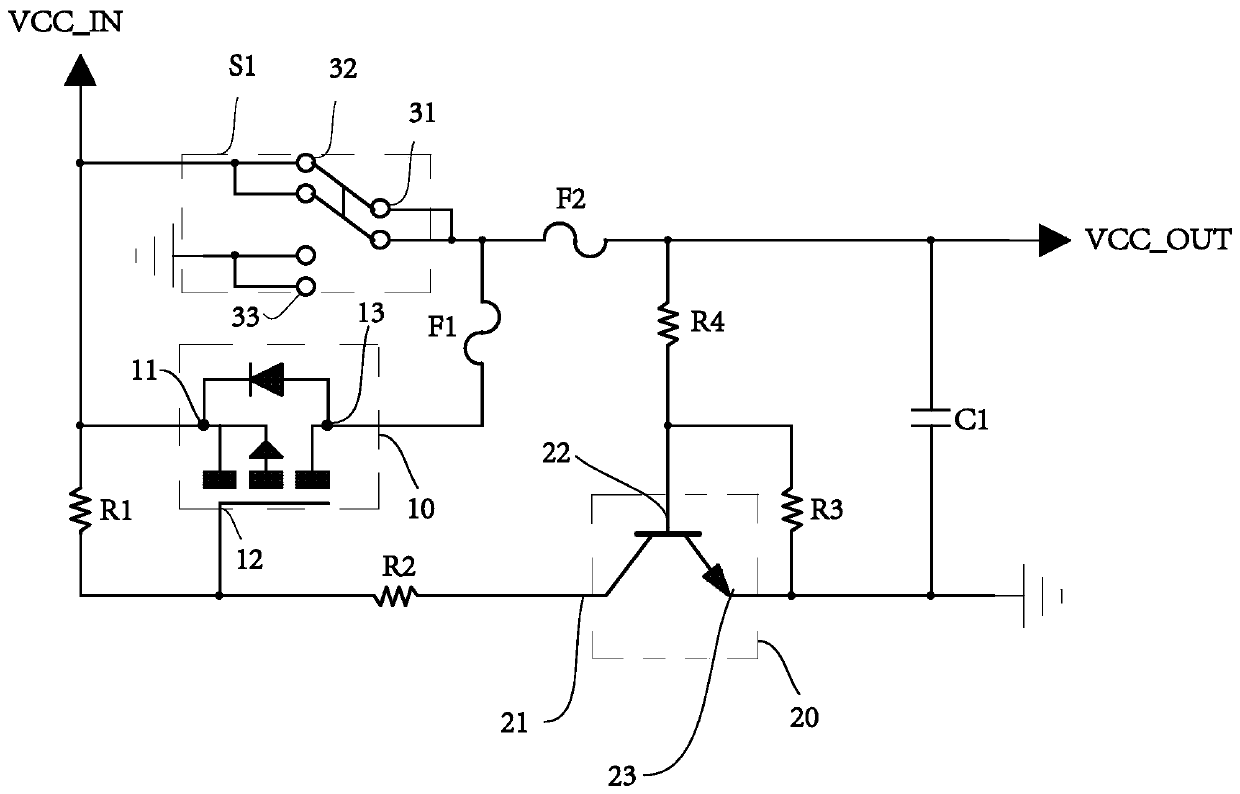
Mechanical switch circuit structure and setting method

A mechanical switch and circuit structure technology, applied in the direction of circuits, electric switches, electrical components, etc., can solve the problems of easy-wear metal of mechanical devices, oxidation of metal components, poor contact of mechanical switch devices, etc., and achieve the effect of ensuring normal operation

Pending Publication Date: 2020-03-24
SHEN ZHEN NEEWER TECH CO LTD
View PDF0 Cites 0 Cited by
  • Summary
  • Abstract
  • Description
  • Claims
  • Application Information

AI Technical Summary

Problems solved by technology

However, compared with semiconductor switching devices, mechanical switching devices have disadvantages that cannot be ignored. For example, because any mechanical device needs to complete the corresponding work through continuous movement, mechanical devices are prone to wear and metal fatigue.
At the same time, since the mechanical switching device is directly exposed to the air, the metal elements in the mechanical switching device may be oxidized and cause poor contact of the mechanical switching device
If the mechanical switch device has poor contact, it will have adverse consequences on the normal operation of the equipment, which will affect the user experience of using mechanical switch products

Method used


Image

  • Mechanical switch circuit structure and setting method

Examples


Embodiment Construction

[0040] Embodiments of the present invention are described in detail below, examples of which are shown in the drawings, wherein the same or similar reference numerals designate the same or similar elements or elements having the same or similar functions throughout. The embodiments described below by referring to the figures are exemplary only for explaining the present invention and should not be construed as limiting the present invention.

[0041] In the description of the present invention, several means one or more, and multiple means more than two. Greater than, less than, exceeding, etc. are understood as not including the original number, and above, below, within, etc. are understood as including the original number. If the description of the first and second is only for the purpose of distinguishing the technical features, it cannot be understood as indicating or implying the relative importance or implicitly indicating the number of the indicated technical features or...


PUM


Abstract

The invention discloses a mechanical switch circuit structure, and the structure comprises a mechanical switch which comprises an output contact, a power contact, and a grounding contact; a first self-locking unit which is arranged between the power supply input end and the power supply output end; a second self-locking unit which is arranged between the power supply input end and the power supplygrounding end; when the power supply contact is conducted with the output contact, the second self-locking unit opens the conduction state and opens the conduction state of the first self-locking unit, and the first self-locking unit outputs a low level; and when the power supply contact and the output contact are in an open circuit state, the output contact is conducted with the grounding contact, the first self-locking unit outputs a high level, and the second self-locking unit is opened to maintain a conduction state. The invention further discloses a setting method of the mechanical switch circuit. Through the mechanical switch circuit structure and the setting method provided by the invention, the normal operation of the circuit can be ensured under the condition of poor contact of the mechanical switch.

Description

technical field [0001] The invention relates to the field of circuit structures, in particular to a mechanical switch circuit structure and a setting method. Background technique [0002] In the prior art, the mechanical switch has the advantages of simple structure, low price, and low calorific value, so it is widely used in various circuit structures. However, compared with semiconductor switching devices, mechanical switching devices have disadvantages that cannot be ignored. For example, since any mechanical device needs to complete the corresponding work through continuous movement, mechanical devices are prone to wear and metal fatigue. At the same time, since the mechanical switching device is directly exposed to the air, metal elements in the mechanical switching device may be oxidized and cause poor contact of the mechanical switching device. If the mechanical switch device has poor contact, it will have adverse consequences on the normal operation of the equipment...

Claims


Application Information

Patent Timeline
IPC IPC(8): H01H9/54
CPCH01H9/54
Inventor 覃忠柯雁
Owner SHEN ZHEN NEEWER TECH CO LTD
Why Eureka
Try Eureka