
Automatic wire plugging device for light source plate

A light source board and automatic wire stripping technology, which is applied in the direction of lighting devices, lighting device parts, connecting device connection/disconnection, etc., can solve the problems of affecting the process, increasing the difficulty of wire insertion, and irregularities, so as to improve production efficiency effect

Pending Publication Date: 2020-03-24
XIAMEN TOPSTAR LIGHTING
View PDF0 Cites 0 Cited by
  • Summary
  • Abstract
  • Description
  • Claims
  • Application Information

AI Technical Summary

Problems solved by technology

Problems in manual plugging: First, the holes on the terminals on the light source board are small, and you need to concentrate when inserting the wires. When plugging in the wires, you need to pinch the wires, otherwise the wires are easy to bend and difficult to insert into the terminal holes. High strength; second, there are main lines and side lines when inserting wires, and it is necessary to distinguish between main lines and side lines. At the same time, when inserting lines, the main line and side lines are required to be inserted into the corresponding terminal holes, so there are characteristics of low production efficiency and error-prone; third. , when the incoming material of the main line and the side line is a cut finished product, the thread end is easy to bend during the transportation and handling process, which increases the difficulty of inserting the line;
[0003] Fourth, when the incoming material is a whole roll, it needs to be stripped by a wire stripping machine first, then sent to the plug-in wire and then manually plugged in. The need for intermediate turnover will also cause the wire end to bend; The finished main line and side line are bent and irregular, which will affect the subsequent process

Method used


Image

  • Automatic wire plugging device for light source plate
  • Automatic wire plugging device for light source plate
  • Automatic wire plugging device for light source plate

Examples


Embodiment Construction

[0047] In order to make the technical problems, technical solutions and beneficial effects to be solved by the present invention clearer and clearer, the present invention will be further described in detail below in conjunction with the accompanying drawings and embodiments. It should be understood that the specific embodiments described here are only used to explain the present invention, not to limit the present invention.

[0048] In the claims, description and above-mentioned drawings of the present invention, unless otherwise clearly defined, the terms "first", "second" or "third" are used to distinguish different objects, not for Describe a specific order.

[0049]In the claims, specification and above-mentioned drawings of the present invention, unless otherwise clearly defined, for orientation words, such as using the terms "center", "transverse", "longitudinal", "horizontal", "vertical", "top" , "Bottom", "Inner", "Outer", "Up", "Down", "Front", "Back", "Left", "Rig...


PUM


Abstract

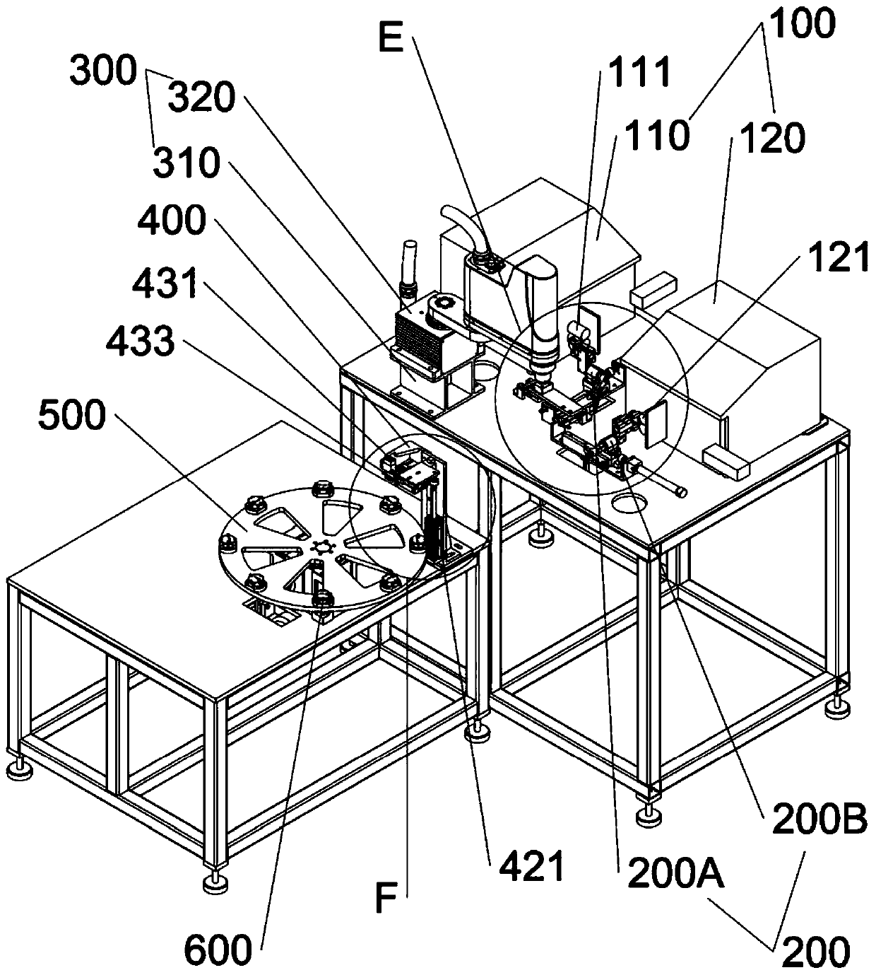
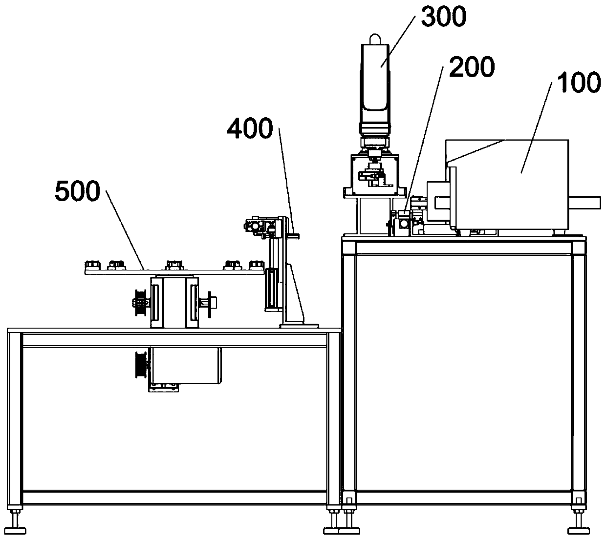
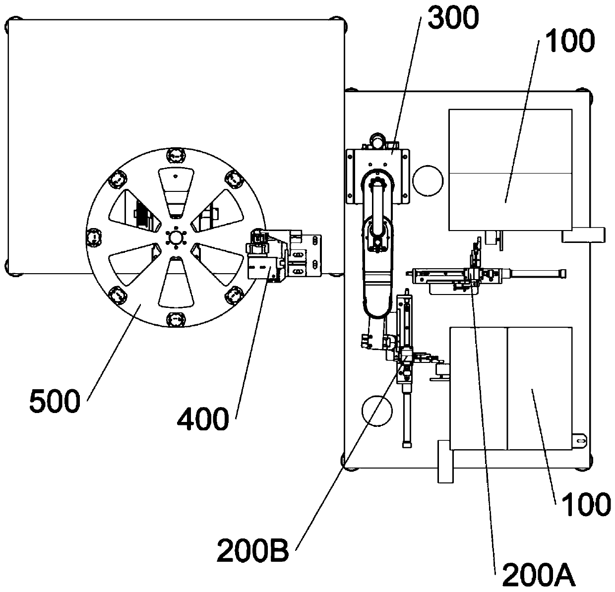
The utility model discloses an automatic wire plugging device for a light source plate, and the device comprises two automatic wire stripping machines. One end, connected with a corner adjusting plate, of a fixed side plate arranged on the wire clamping turnover mechanism is provided with an arc groove. First wire clamping pneumatic claws of the main wire clamping mechanism and the side wire clamping mechanism are provided with two first wire clamping fingers; cam followers are arranged on moving swing pieces of the main line turnover mechanism and the side line turnover mechanism, one ends ofthe cam followers are movably connected with line clamping turnover rotating shafts, and the other ends of the cam followers are connected with turnover tension springs. The main line translation mechanism and the side line translation mechanism comprise moving seats which translate along the first sliding rails so that the line clamping turnover rotating shafts can be installed in the moving seats, and the other ends are connected with the first line clamping pneumatic claws. The robot wire clamping mechanism is provided with two second wire clamping pneumatic claws. The plug wire moving mechanism is provided with a third clamping pneumatic claw; the wire guiding mechanism is provided with an upper guide block and a lower guide block, and when one wire blocking plate is located below thelower guide block, a third wire clamping finger is arranged between the wire blocking plate and the lower guide block. According to the device, middle turnover transportation is reduced, the percentof pass of main wire and side wire insertion on the light source plate is improved, and the production efficiency is high.

Description

technical field [0001] The invention belongs to the technical field of lamp lighting production, and in particular relates to an automatic wire insertion device for a light source board. Background technique [0002] At present, the power lines on the light source board of the lamp lighting manufacturing workshop include main lines and side lines, and the main lines and side lines are mostly inserted manually. Problems in manual plugging: First, the holes on the terminals on the light source board are small, and you need to concentrate when inserting the wires. When plugging in the wires, you need to pinch the wires, otherwise the wires are easy to bend and difficult to insert into the terminal holes. High strength; second, there are main lines and side lines when inserting wires, and it is necessary to distinguish between main lines and side lines. At the same time, when inserting lines, the main line and side lines are required to be inserted into the corresponding termina...

Claims


Application Information

Patent Timeline
IPC IPC(8): H01R43/26F21V23/06
CPCF21V23/06H01R43/26
Inventor 陈宝贵杨鸿武
Owner XIAMEN TOPSTAR LIGHTING
Learn More