Fluid reactor

A technology for reactors and fluids, applied in fluid mixers, chemical/physical/physicochemical nozzle reactors, chemical liquid solidification, etc., can solve problems such as insufficient particle size distribution

Active Publication Date: 2020-03-24
LEON NANODRUGS GMBH
View PDF6 Cites 0 Cited by
  • Summary
  • Abstract
  • Description
  • Claims
  • Application Information

AI Technical Summary

Problems solved by technology

However, in existing fluid reactors, even under ideal operating conditions, the achievable particle size distributions are not broad enough for some applications and further measures to separate the particle sizes are required

Method used


Image

  • Fluid reactor
  • Fluid reactor
  • Fluid reactor

Examples


Embodiment Construction

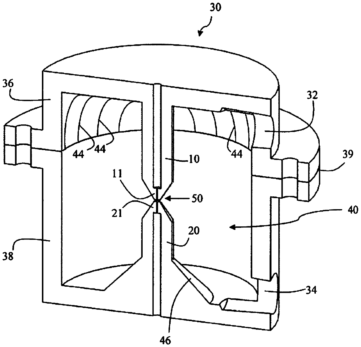
[0013] In the context of the present invention, "collinear" refers not only to angles of 0° (same direction) or 180° (opposite directions), but also includes some deviations from this interaction angle that can be seen in practice. The term "collinear" herein is intended to include interaction angles of -10° to +10°, ie 170° to 190°.

[0014] In the context of the present invention, "collinear" not only means that two interacting jets or nozzles are aligned or located on the same axis, but actually includes possible displacement deviations on either side of the jet or nozzle axis. Ideally, the two jets should overlap 100%, ie the two jets or nozzle axes are aligned. However, the term "collinear" also includes overlapping ratios of 50% and above, 70% and above. The degree of this overlap also depends on the jet profile of the free jet coming out of the nozzle. Those skilled in the art are aware of the relationship therein.

[0015] In the following, specific embodiments of t...


PUM


Abstract

The invention relates to a fluid reactor for generating particulate fluids by collision, having a housing (30), which encloses a collision chamber (40), a first fluid nozzle (10) and a second fluid nozzle (20) oriented opposite thereto in a collinear manner, which is located directly opposite the first fluid nozzle (10) in the jet direction of the nozzles (10, 20) in a common collision zone (50),at least one rinsing fluid inlet (32) into the collision chamber (40) arranged on the side (36) of the first fluid nozzle (10) and at least one product outlet (34) out of the collision chamber (40) arranged on the side (38) of the second fluid nozzle (20).

Description

technical field [0001] The present invention relates to fluid reactors, in particular so-called impact jet reactors, for the production of nanoparticles by precipitation from a fluid medium. The present invention relates to methods and means for the preparation of nanoparticles with a narrow particle size distribution from solution, especially for use in chemical or pharmaceutical products. Background technique [0002] Nanoparticles of a substance or a mixture of substances may be obtained by precipitation from a solution of the substance or a mixture of substances or its precursors when a liquid in which the substance or its precursors are dissolved encounters a precipitation bath under high pressure and thus at high speed . This leads to atomization of the liquid and thus to the formation of precipitation products in the form of nanoparticle structures. One technical implementation is known as the "shock jet" method. For this, it is necessary to use a fluid reactor in ...

Claims


Application Information

Patent Timeline
IPC IPC(8): B01J19/26B01J4/00B01F5/02B01J2/02
CPCB01J19/26B01J2/02B01J4/002B01F25/23B01J2/04B01J19/06B01J2219/00601
Inventor 莫里兹·瓦尔特马里奥·博特
Owner LEON NANODRUGS GMBH
Why Eureka
Try Eureka