
Glue dispensing device and glue dispensing method

A dispensing device and dispensing technology, which is applied to the device and coating of the surface coating liquid, can solve the problems of inability to confirm the dispensing effect of the dispensing needle, high cost of the optical fiber sensor, and long calibration time, etc., to achieve calibration The effect of short time required, improved calibration results, and low cost

Active Publication Date: 2020-03-27
SHENZHENSHI YUZHAN PRECISION TECH CO LTD
View PDF19 Cites 3 Cited by
  • Summary
  • Abstract
  • Description
  • Claims
  • Application Information

AI Technical Summary

Problems solved by technology

At present, the calibration process of the dispensing needle mainly uses three groups of optical fiber sensors to correct the deviation in three directions, and the calibration of the optical fiber sensor is indirect. It can only determine the position of the dispensing needle, and cannot correct the position of the dispensing needle. The effect of dispensing is confirmed, and abnormalities may occur during actual dispensing, and the cost of the three sets of optical fiber sensors is relatively high, taking up a large space and taking a long time to correct

Method used

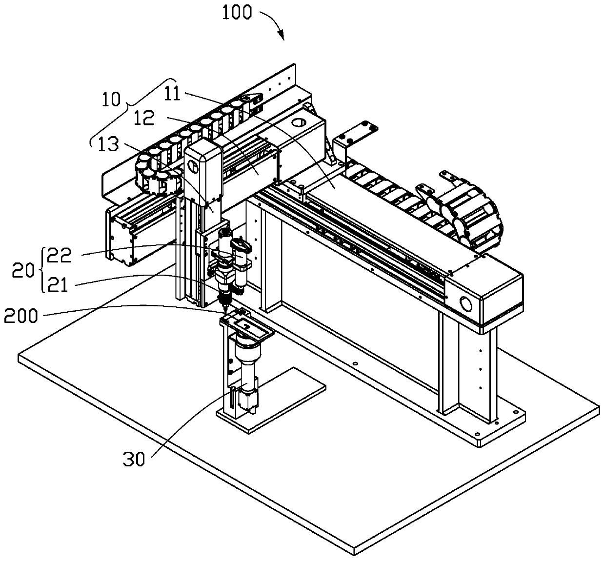
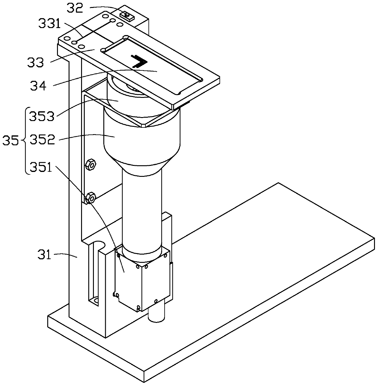
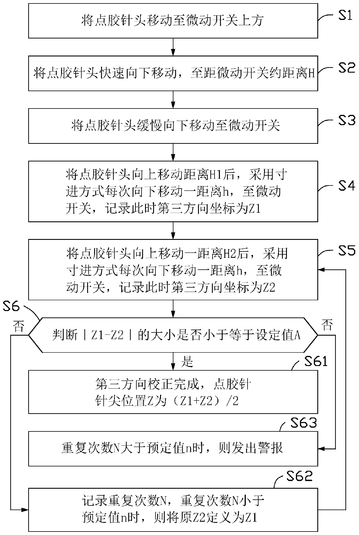

Image

  • Glue dispensing device and glue dispensing method
  • Glue dispensing device and glue dispensing method
  • Glue dispensing device and glue dispensing method

Examples


Embodiment Construction

[0025] The following will clearly and completely describe the technical solutions in the embodiments of the present invention with reference to the accompanying drawings in the embodiments of the present invention. Obviously, the described embodiments are only some of the embodiments of the present invention, not all of them. Based on the embodiments of the present invention, all other embodiments obtained by persons of ordinary skill in the art without making creative efforts belong to the protection scope of the present invention.

[0026] It should be noted that when an element is considered to be "connected" to another element, it may be directly connected to the other element or there may be an intervening element at the same time. When an element is referred to as being "disposed on" another element, it can be directly disposed on the other element or intervening elements may also be present.

[0027] Unless otherwise defined, all technical and scientific terms used here...


PUM


Abstract

The invention provides a glue dispensing device. The glue dispensing device comprises a glue dispensing mechanism and a correction mechanism. The glue dispensing mechanism is used for forming a firstglue path. The correction mechanism is coupled to the glue dispensing mechanism and comprises a detection unit. The detection unit is used for detecting the glue width of the first glue path and detecting the distance difference between the first glue path and a reference line set. The glue dispensing mechanism forms a second glue path according to the glue width and the distance difference. The invention further provides a glue dispensing method of the glue dispensing device.

Description

technical field [0001] The invention relates to a glue dispensing device and a glue dispensing method. Background technique [0002] During the dispensing process, the needle of the dispensing needle is easy to be blocked, and it is easy to hit the needle. It is often necessary to replace the dispensing needle. Ensure the normal operation of dispensing. At present, the calibration process of the dispensing needle mainly uses three groups of optical fiber sensors to correct the deviation in three directions, and the calibration of the optical fiber sensor is indirect. It can only determine the position of the dispensing needle, and cannot correct the position of the dispensing needle. The effect of dispensing is confirmed, and abnormalities may occur during actual dispensing, and the cost of the three sets of optical fiber sensors is relatively high, taking up a large space and taking a long time to correct. Contents of the invention [0003] In view of the above situatio...

Claims


Application Information

Patent Timeline
Patent Type & Authority Applications(China)
IPC IPC(8): B05C5/02B05D1/26
CPCB05C5/02B05D1/26
Inventor 汤爱军陈石王卫峥林俊宇杨波廖建国
Owner SHENZHENSHI YUZHAN PRECISION TECH CO LTD
Learn More