
High-voltage bushing flange spinning device and spinning method

A high-pressure sleeve and flange technology, applied in the field of spinning forming equipment, can solve the problems of long cycle and cumbersome process, and achieve the effect of convenient operation, fast and simple process, and easy to place and take out.

Inactive Publication Date: 2020-03-27
SHAANXI AEROSPACE ELECTROMECHANICAL ENVIRONMENTAL ENG DESIGNING INST CO LTD
View PDF9 Cites 1 Cited by
  • Summary
  • Abstract
  • Description
  • Claims
  • Application Information

AI Technical Summary

Problems solved by technology

[0004] The main purpose of the present invention is to solve the technical problem that the upper and lower flanges of the high-voltage capacitor porcelain bushing are cast and formed in the prior art, the process is cumbersome and the cycle is long, and to provide a high-voltage bushing flange spinning device and spinning method

Method used


Image

  • High-voltage bushing flange spinning device and spinning method
  • High-voltage bushing flange spinning device and spinning method
  • High-voltage bushing flange spinning device and spinning method

Examples


Embodiment 1

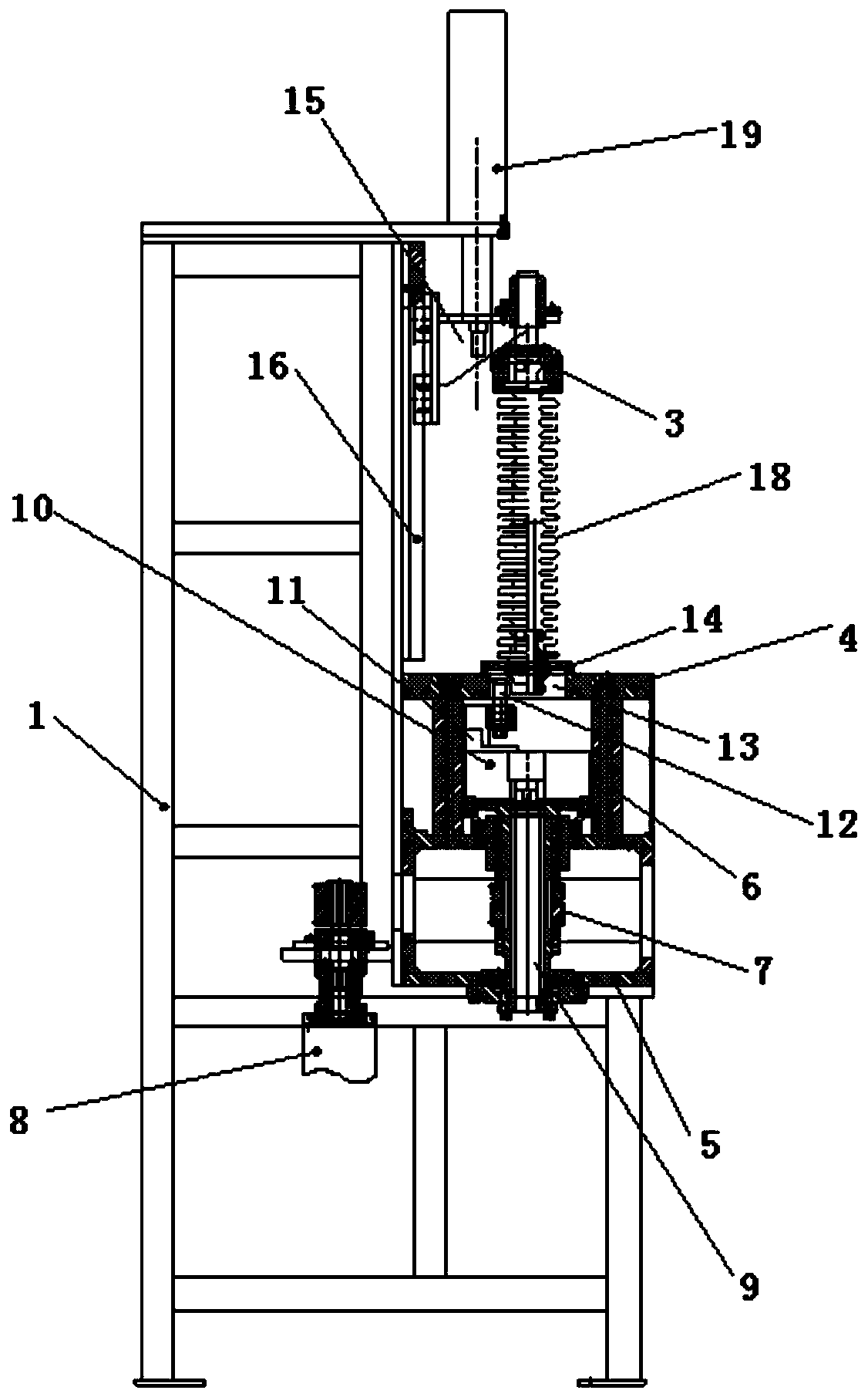
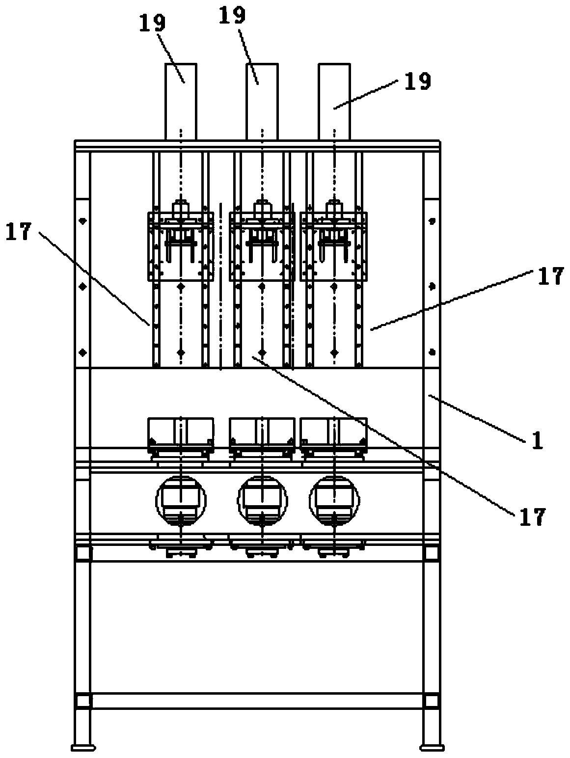
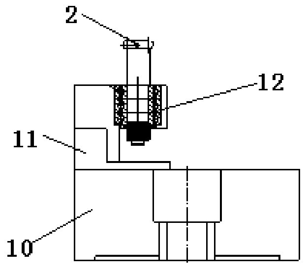
[0036] like figure 1 and figure 2 , a high-voltage bushing flange spinning device, including a frame 1 and three sets of spinning mechanisms 17 arranged on the frame 1, and the three sets of spinning mechanisms are arranged side by side. The spinning mechanism 17 includes a cylinder 19 installed on the frame 1; the cylinder 19 drives the top assembly 3 to move up and down, the top assembly 3 is installed on the sliding bracket 15, and the sliding bracket 15 cooperates with the slide rail 16 fixed on the frame 1 , The sliding bracket 15 is installed on the output end of the cylinder 19 . A panel 4 is provided below the top assembly 3 , a spindle box 5 is provided below the panel 4 , and the panel 4 is connected to the spindle box 5 through a column 6 . A through hole 13 is opened on the panel 4, and a hollow positioning bracket 14 is erected above the through hole 13, and the center of the through hole 13 and the center of the tip assembly 3 are located on the same straight ...

Embodiment 2

[0038] A high-voltage bushing flange spinning device includes a frame 1 and a group of spinning mechanisms 17 arranged on the frame 1 , and the spinning mechanism 17 is located in the middle of the frame 1 . The spinning mechanism 17 includes a cylinder 19 installed on the frame 1; the cylinder 19 drives the top assembly 3 to move up and down, the top assembly 3 is installed on the sliding bracket 15, and the sliding bracket 15 cooperates with the slide rail 16 fixed on the frame 1 , The sliding bracket 15 is installed on the output end of the cylinder 19 . A panel 4 is provided below the top assembly 3 , a spindle box 5 is provided below the panel 4 , and the panel 4 is connected to the spindle box 5 through a column 6 . A through hole 13 is opened on the panel 4, and a hollow positioning bracket 14 is erected above the through hole 13, and the center of the through hole 13 and the center of the tip assembly 3 are located on the same straight line. The bottom of frame 1 is p...

Embodiment 3

[0040]A high-voltage bushing flange spinning device includes a frame 1 and two sets of spinning mechanisms 17 arranged on the frame 1 , and the spinning mechanisms 17 are located in the middle of the frame 1 . The spinning mechanism 17 includes a cylinder 19 installed on the frame 1; the cylinder 19 drives the top assembly 3 to move up and down, the top assembly 3 is installed on the sliding bracket 15, and the sliding bracket 15 cooperates with the slide rail 16 fixed on the frame 1 , The sliding bracket 15 is installed on the output end of the cylinder 19 . A panel 4 is provided below the top assembly 3 , a spindle box 5 is provided below the panel 4 , and the panel 4 is connected to the spindle box 5 through a column 6 . A through hole 13 is opened on the panel 4, and a hollow positioning bracket 14 is erected above the through hole 13, and the center of the through hole 13 and the center of the tip assembly 3 are located on the same straight line. The bottom of frame 1 is...


PUM


Abstract

The invention belongs to spinning forming equipment and method for a ceramic bushing in a high-voltage capacitor, and provides a high-voltage bushing flange spinning device and spinning method in order to solve the technical problems that when an upper flange and a lower flange of a high-voltage capacitor ceramic bushing adopt a pouring forming method, the process is tedious, and the period is long. The high-voltage bushing flange spinning device comprises a rack and at least one group of spinning mechanisms; each spinning mechanism comprises a driving device, each driving device drives a tipassembly to vertically move, a panel is arranged under each tip assembly and connected with a spindle box through stand columns, and each panel is provided with a through hole of which the center is located on a same straight line with the center of the corresponding tip assembly; and driving motors drive rotation shafts to rotate, the upper ends of the rotation shafts penetrate through the tops of the spindle boxes, electric chunks are installed at the upper ends of the rotation shafts, spindles are sleeved with the rotation shafts, and spinning cutters located in the through holes are installed on clamping claws of the electric chunks. The spinning method is based on the device. A workpiece is compressed by the tip assemblies, the rotating motors drives the spinning cutters to rotate through the rotation shafts, and the spinning cutters simultaneously do radial reciprocating motion to complete spinning.

Description

technical field [0001] The invention belongs to spinning forming equipment and a method for porcelain sleeves in high-voltage capacitors, and in particular relates to a high-voltage bushing flange spinning device and spinning method. Background technique [0002] High-voltage capacitors are important equipment in power systems, which can effectively improve the voltage quality of power systems and enhance the transmission capacity of transmission lines. The bushing of high-voltage capacitor is one of the important components of capacitor equipment, which is used for insulation and support. [0003] The porcelain sleeve and the capacitor body need to be connected through flanges. At present, the flange is shaped and positioned by pouring, and epoxy resin is often used for bonding. The production process of this method is cumbersome and the cycle is long. Contents of the invention [0004] The main purpose of the present invention is to solve the technical problem that the ...

Claims


Application Information

Patent Timeline
Patent Type & Authority Applications(China)
IPC IPC(8): B21D22/14B21D43/00B21D39/00
CPCB21D22/14B21D39/00B21D43/003
Inventor 代萌萌龙创平徐敏胡亚孙红杰冯英龙王坚马静徐造林曹红伟段艳丹
Owner SHAANXI AEROSPACE ELECTROMECHANICAL ENVIRONMENTAL ENG DESIGNING INST CO LTD
Learn More