
An auxiliary cable clamp installation device

A technology of installation device and cable clamp, applied in the direction of overhead line/cable equipment, etc., can solve the problems of low construction efficiency, large elasticity of the cable itself, and increased difficulty.

Active Publication Date: 2020-10-30
RES INST OF ECONOMICS & TECH STATE GRID SHANDONG ELECTRIC POWER +3
View PDF8 Cites 0 Cited by
  • Summary
  • Abstract
  • Description
  • Claims
  • Application Information

AI Technical Summary

Problems solved by technology

[0002] It is very important to ensure the safe and stable operation of the power grid in today's society. The cable is erected on the pole or building through the street yard. The fixing of the cable end is generally to bend the cable end around the street yard and then bend it Under tension, bind or fix the bent cable ends; at present, construction workers usually use traditional methods such as manpower or simple tools to bend the cable ends and use binding wires to bind and fix the bent cable ends. Because the diameter of the cable is relatively thick, it is difficult for personnel working at heights to bend and tighten the cable only by manpower or simple tools, and the cable itself is very elastic when it is bent, and it is easy to bounce or slip off from the hands or simple tools. Increased the difficulty of construction
The cable clamp generally includes a male clamp and a female clamp. When the cable clamp is fastened, the male clamp and the female clamp need to be aligned and tightened with fastening bolts. At this time, the construction personnel need to pinch the male clamp and the female clamp of the cable clamp with one hand. The female clip, the other hand uses a wrench to tighten multiple fastening bolts in sequence, and the construction efficiency is low

Method used


Image

  • An auxiliary cable clamp installation device
  • An auxiliary cable clamp installation device
  • An auxiliary cable clamp installation device

Examples


Embodiment Construction

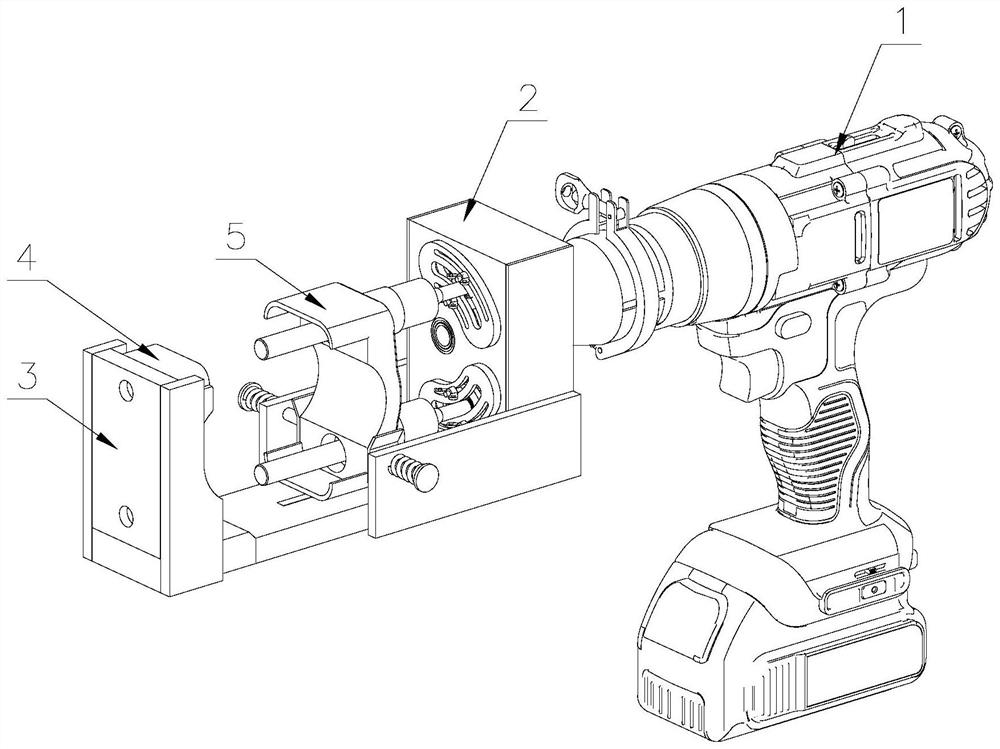
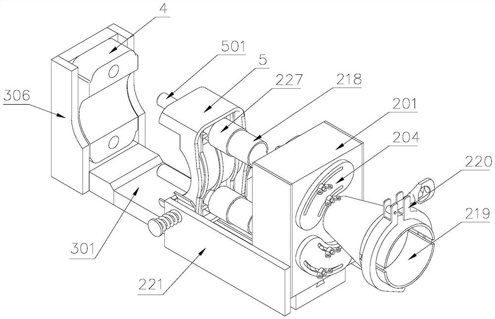
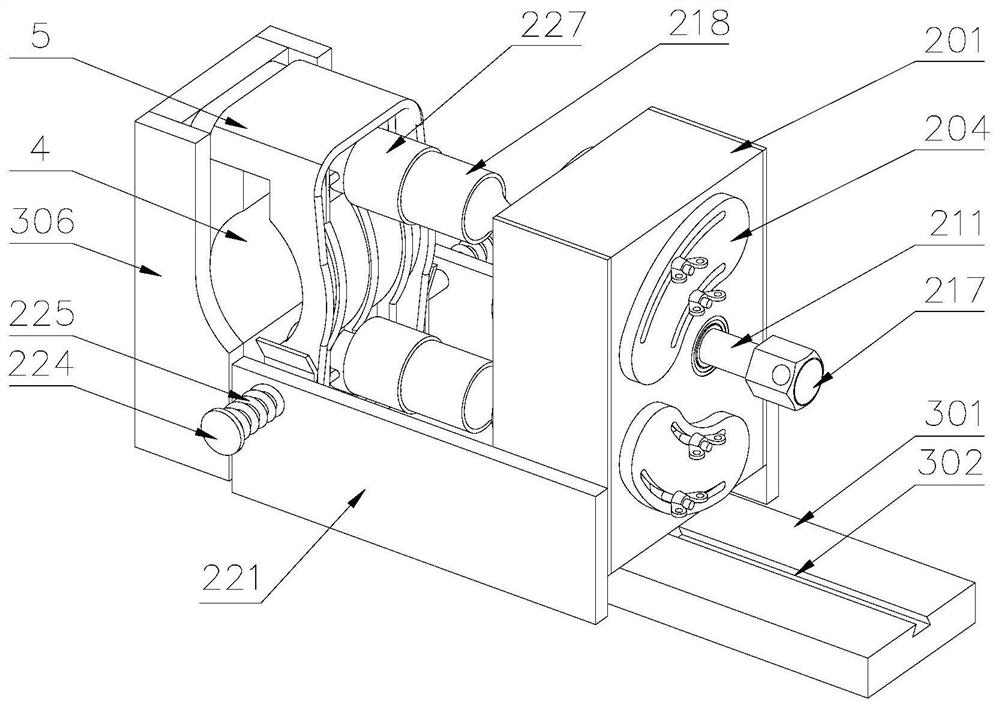
[0035] Attached below Figure 1-7 , clearly and completely describe the technical solutions in the embodiments of the present invention, obviously, the described embodiments are only some of the embodiments of the present invention, not all of them. Based on the embodiments of the present invention, all other embodiments obtained by persons of ordinary skill in the art without making creative efforts belong to the protection scope of the present invention.

[0036] In describing the present invention, it should be understood that the terms "longitudinal", "transverse", "upper", "lower", "front", "rear", "left", "right", "vertical", The orientations or positional relationships indicated by "horizontal", "top", "bottom", "inner", "outer", etc. are based on the orientations or positional relationships shown in the drawings, and are only for the convenience of describing the present invention, rather than indicating or It should not be construed as limiting the invention by imply...


PUM


Abstract

The invention discloses a cable clamp auxiliary installation device. A fixing device comprises a bottom plate, a vertical plate arranged at one end of the bottom plate and the second clamping plates arranged at the two sides of the vertical plate, and a male clamp is installed between the second clamping plates at the two sides. A driving device is arranged at the other end of the bottom plate, adriving gear is mounted on a spindle, and the two ends of the spindle are mounted in the spindle holes through bearings. The two driven gears are symmetrically distributed at the two sides of the driving gear and are installed on a rotating shaft, a connector is arranged at one end of the rotating shaft, and a wrench sleeve is detachably installed at one end of the connector. One end of a fastening bolt is inserted into a female clamp, and the other end of the fastening bolt is installed in the wrench sleeve. According to the cable clamp, the fixing device is arranged, the driving device is arranged on the fixing device, and multiple output shafts are arranged on the driving device; the connector is arranged at one end of each output shaft, the wrench sleeve is arranged at one end of eachconnector, and the multiple fastening bolts are tightened simultaneously through the wrench sleeves, so that the installation efficiency of a cable clamp is improved.

Description

technical field [0001] The invention belongs to the technical field of electric power construction, in particular to an auxiliary cable clamp installation device. Background technique [0002] It is very important to ensure the safe and stable operation of the power grid in today's society. The cable is erected on the pole or building through the street yard. The fixing of the cable end is generally to bend the cable end around the street yard and then bend it Under tension, bind or fix the bent cable ends; at present, construction workers usually use traditional methods such as manpower or simple tools to bend the cable ends and use binding wires to bind and fix the bent cable ends. Because the diameter of the cable is relatively thick, it is difficult for personnel working at heights to bend and tighten the cable only by manpower or simple tools, and the cable itself is very elastic when it is bent, and it is easy to bounce or slip off from the hands or simple tools. Incr...

Claims


Application Information

Patent Timeline
Patent Type & Authority Patents(China)
IPC IPC(8): H02G1/04
CPCH02G1/04
Inventor 韩义成黄鹏宋来森姜兆庆
Owner RES INST OF ECONOMICS & TECH STATE GRID SHANDONG ELECTRIC POWER
Learn More