
Rotor and motor

A rotor and permanent magnet technology, applied in the field of rotors and motors, can solve the problems of permanent magnet magnetization process influence, easy deviation, high precision, etc., achieve the effect of optimizing the pole arc coefficient, simplifying the magnetization process, and improving the magnetization structure

Inactive Publication Date: 2020-03-27
ZHUHAI KAIBANG MOTOR MFR +1
View PDF5 Cites 0 Cited by
  • Summary
  • Abstract
  • Description
  • Claims
  • Application Information

AI Technical Summary

Problems solved by technology

[0002] At present, the DC frequency conversion floor fan motors on the market are magnetized by opening positioning holes on the rotor shell to position the magnetic poles. However, when the magnetic strips are rolled into a ring, the circumferential positioning requires high accuracy, and deviations are prone to occur, which will damage the permanent magnets. The magnetization process has a significant impact on

Method used


Image

  • Rotor and motor
  • Rotor and motor
  • Rotor and motor

Examples


Embodiment Construction

[0035] In order to facilitate the understanding of the present invention, the present invention will be described more fully below with reference to the associated drawings. Preferred embodiments of the invention are shown in the accompanying drawings. However, the present invention can be embodied in many different forms and is not limited to the embodiments described herein.

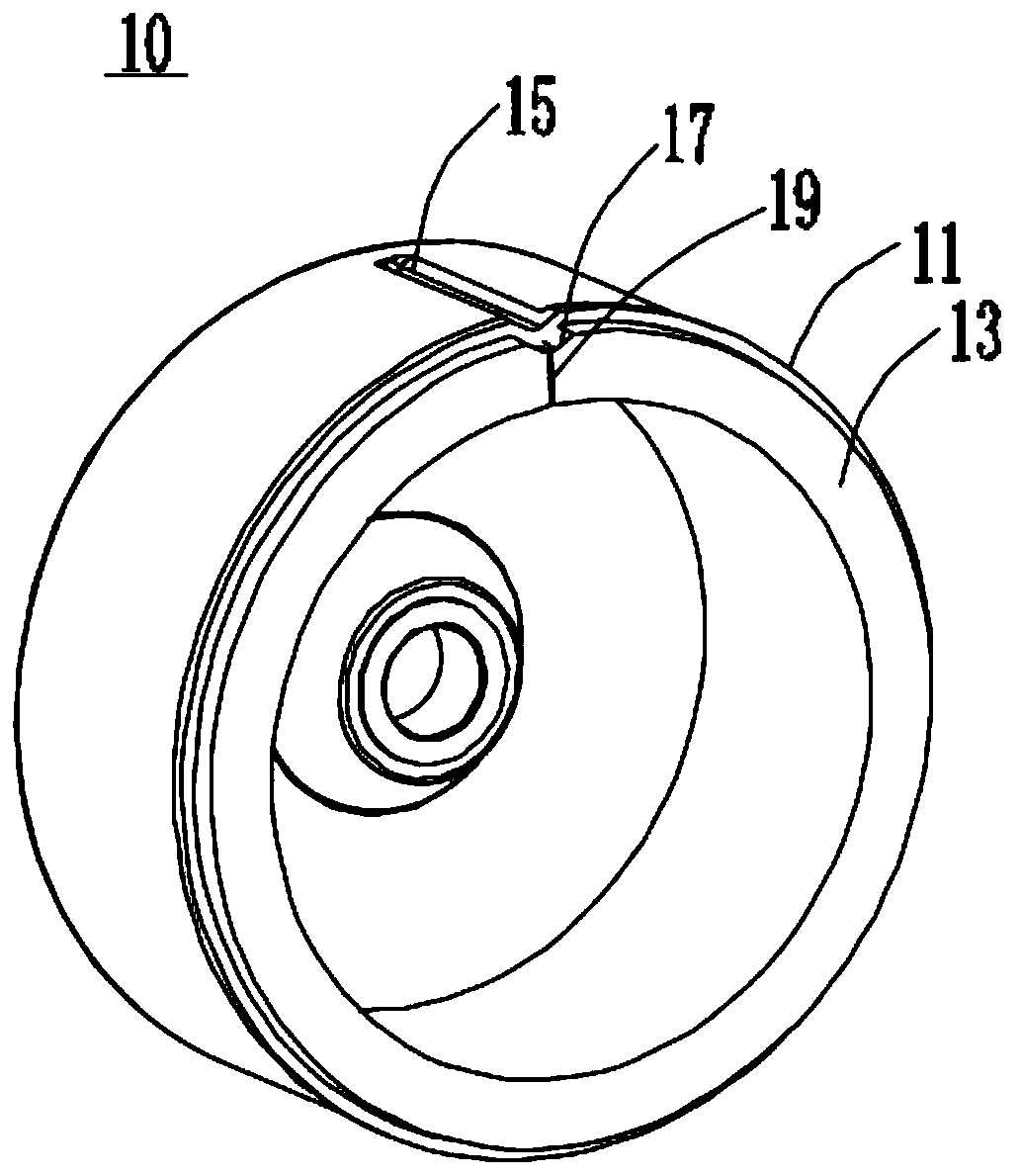
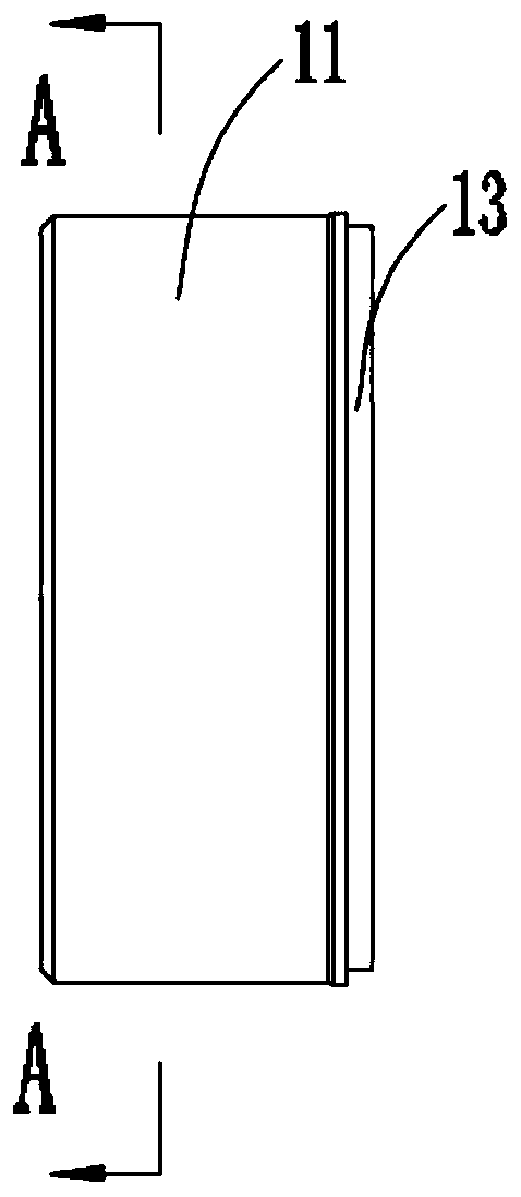
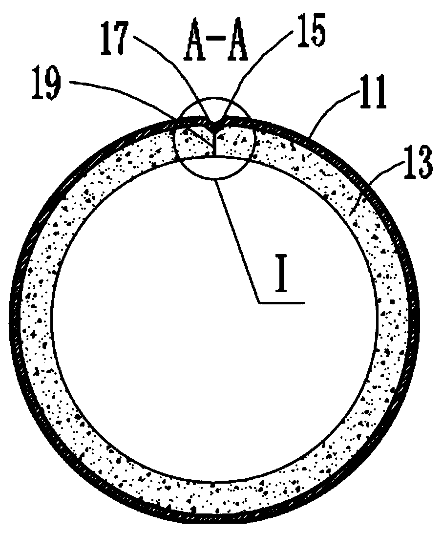
[0036] Such as Figure 1-6 As shown, a rotor 10 includes a rotor casing 11 and a permanent magnet 13 sleeved inside the rotor casing 11. The rotor casing 11 is provided with a concave portion 15 that is concave toward its center, and the permanent magnet 13 is provided with a concave portion that is concave toward its center. The groove 17, the concave part 15 is matched with the groove 17.

[0037] Wherein, the permanent magnet 13 is provided with a splicing seam 19, and the splicing seam 19 is located at the groove 17. When the recessed part 15 cooperates with the groove 17, the deviation angle of ...


PUM


Abstract

The invention provides a rotor and a motor. The rotor comprises a rotor shell and a permanent magnet sleeved in the rotor shell; the rotor shell is provided with a concave part which is concave towards the center of the rotor shell; the permanent magnet is provided with a groove recessed towards the center of the permanent magnet. Wherein the concave part is matched with the groove, the permanentmagnet is provided with a splicing seam, the splicing seam is located at the groove, and when the concave part is matched with the groove, the deviation angle of the splicing seam is controlled withinthe preset deviation angle range of the splicing seam. The magnetizing process of the permanent magnet can be simplified, the magnetizing structure of the permanent magnet is improved, and the deviation angle of a splicing seam is controlled.

Description

technical field [0001] The present invention relates to the technical field of motors, in particular to a rotor and a motor. Background technique [0002] At present, the DC frequency conversion floor fan motors on the market are magnetized by opening positioning holes on the rotor shell to position the magnetic poles. However, when the magnetic strips are rolled into a ring, the circumferential positioning requires high accuracy, and deviations are prone to occur, which will damage the permanent magnets. The magnetization process has a significant impact. In view of the above problems, it is necessary to design a rotor and a motor that can simplify the magnetization process of the permanent magnet, improve the magnetization structure of the permanent magnet, and control the deviation angle of the splicing seam. Contents of the invention [0003] Aiming at the above-mentioned problems in the prior art, the present application proposes a rotor and a motor, which can simpli...

Claims


Application Information

Patent Timeline
Patent Type & Authority Applications(China)
IPC IPC(8): H02K1/27H02K15/03
CPCH02K1/2786H02K15/03H02K2213/03
Inventor 吴泽华冯奕冠李庆高晓峰李如鹏李万山
Owner ZHUHAI KAIBANG MOTOR MFR
Learn More