A template polishing equipment for electronic equipment appearance spraying

A technology for electronic equipment and appearance, which is applied in the field of template polishing equipment for electronic equipment appearance spraying, which can solve problems such as difficult collection of polishing liquid and inability to integrate template polishing operations, so as to save manual operations, improve recycling capabilities, and improve operation. efficiency effect

Inactive Publication Date: 2021-08-17
湖南博友等离子自动化设备有限公司
View PDF11 Cites 0 Cited by
  • Summary
  • Abstract
  • Description
  • Claims
  • Application Information

AI Technical Summary

Problems solved by technology

[0005] In order to overcome the shortcomings of being unable to perform integrated polishing on the template and collecting the used polishing fluid, the technical problem to be solved is to provide an electronic equipment appearance spraying that can perform integrated polishing on the template and facilitate the collection of used polishing fluid Polishing equipment with templates

Method used


Image

  • A template polishing equipment for electronic equipment appearance spraying
  • A template polishing equipment for electronic equipment appearance spraying
  • A template polishing equipment for electronic equipment appearance spraying

Examples


Embodiment 1

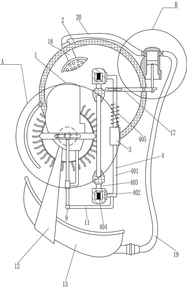
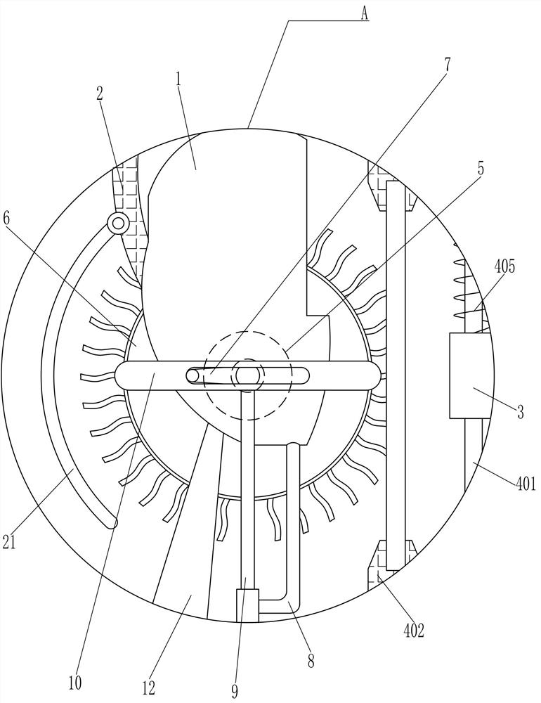
[0019] A template polishing equipment for electronic equipment appearance spraying, such as Figure 1-2 As shown, it includes a mounting plate 1, an arc frame 2, a guide sleeve 3, a clamping device 4, a biaxial motor 5, a brush wheel 6, a push rod 7, a guide frame 8, a T-shaped bar 9, and a first groove bar 10 , connecting rod 11, triangular plate 12 and arc-shaped basin 13, the top of the installation plate 1 is provided with an arc-shaped frame 2, the end of the arc-shaped frame 2 is provided with a guide sleeve 3, and the guide sleeve 3 is provided with a clamping device 4, behind the installation plate 1 There is a biaxial motor 5 on the side, the rear output shaft of the biaxial motor 5 is connected with a brush wheel 6, the front output shaft of the biaxial motor 5 is connected with a push rod 7, the bottom of the mounting plate 1 is provided with a guide frame 8, and the inside of the guide frame 8 Slidingly connected with a T-shaped bar 9, the top of the T-shaped bar 9...

Embodiment 2

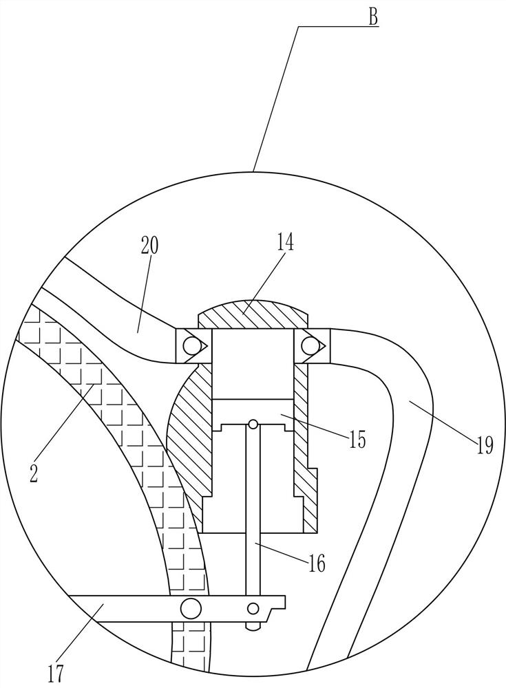
[0023] On the basis of Example 1, such as figure 1 and image 3 Shown, also comprise pump body 14, piston 15, rotating rod 16, the second groove bar 17, spray nozzle 18, liquid inlet pipe 19 and discharge pipe 20, arc frame 2 is provided with pump body 14, pump body 14 The inner sliding type is connected with the piston 15, the bottom of the piston 15 is connected with the rotating rod 16, and the front part of the arc frame 2 is connected with the second groove rod 17 in a rotating type, and one end of the second groove rod 17 is connected with the rotation rod 16 bottom. Connection, the upper part of the guide rod 401 is slidingly matched with the other side of the second groove rod 17, the upper part of the arc frame 2 is provided with a nozzle 18, the nozzle 18 is connected with a drain pipe 20, the drain pipe 20 is connected with the pump body 14, and the pump body The other side of 14 is connected with a liquid inlet pipe 19, and the end of the liquid inlet pipe 19 is c...

Embodiment 3

[0026] On the basis of Example 2, such as figure 2 As shown, an arc-shaped baffle 21 is also included, and one side of the arc-shaped frame 2 is rotatably connected to the arc-shaped baffle 21 .

[0027] Through the arc-shaped baffle 21 , the polishing fluid on the brush wheel 6 can be effectively diverted, thereby achieving the effect of preventing random splashing of the polishing fluid.


PUM


Abstract

The invention relates to a template polishing device, in particular to a template polishing device for external appearance spraying of electronic equipment. The technical problem of the present invention is how to provide a template polishing equipment for electronic equipment appearance spraying, which can perform integrated polishing operation on the template and facilitate the collection of used polishing liquid. A template polishing device for electronic equipment appearance spraying, including a mounting plate, an arc frame, etc.; the top of the mounting plate is provided with an arc frame. In the present invention, through the cooperation of the brush wheel and the clamping device, it is convenient to fully polish the surface of the template, and the excess polishing liquid is collected through the arc-shaped basin, which improves the resource recycling ability of the equipment. With the cooperation of the device, the equipment can automatically extract and spray the polishing liquid, which saves the manual operation steps of the workers. Through the curved baffle, the polishing liquid on the brush wheel can be effectively diverted to prevent the polishing liquid from splashing randomly. shot effect.

Description

technical field [0001] The invention relates to a template polishing device, in particular to a template polishing device for external appearance spraying of electronic equipment. Background technique [0002] In the production process of electronic equipment, in order to mark it, people need to spray the electronic equipment. In the spraying operation, it is often necessary to use the template to cooperate with the spraying equipment. The template is stained with paint after the spraying operation is completed, so it is necessary It is cleaned and polished for secondary use. [0003] The traditional polishing method is manual polishing by workers. Although this method is relatively straightforward to operate, the steps are complicated, which is not conducive to speeding up the work efficiency. A lot of waste. [0004] Therefore, it is necessary to develop a template polishing equipment for electronic equipment appearance spraying that can perform integrated polishing oper...

Claims


Application Information

Patent Timeline
Patent Type & Authority Patents(China)
IPC IPC(8): B24B29/02B24B41/06B24B57/02B24B57/00
CPCB24B29/005B24B29/02B24B41/06B24B57/00B24B57/02
Inventor 游飞
Owner 湖南博友等离子自动化设备有限公司
Why Eureka
Try Eureka