Chain cleaning machine

A cleaning machine and chain technology, applied in the field of cleaning machines, can solve the problems of reducing cleaning efficiency, prone to corrosion, low cleaning efficiency, etc., and achieve the effects of improving cleaning efficiency, flexible operation and convenient installation.

Active Publication Date: 2021-08-24
CHINA NUCLEAR POWER TECH RES INST CO LTD +2
View PDF6 Cites 0 Cited by
  • Summary
  • Abstract
  • Description
  • Claims
  • Application Information

AI Technical Summary

Problems solved by technology

[0003] At present, the commonly used cleaning machine for the intake canal of nuclear power plants in China is a steel wire rope traction rake bucket cleaning machine, but this cleaning machine has the following disadvantages: First, this steel wire rope traction rake bucket cleaning machine has only one cleaning bucket. The cleaning rake bucket is pulled by the wire rope to complete the actions of lifting, meshing with the grid and turning over. However, since this kind of wire rope traction bucket type cleaning machine has only one cleaning bucket, the cleaning process takes a long time. The cleaning process stops intermittently, the cleaning efficiency is low, and the water intake channel of the nuclear power plant is easily blocked; second, after the cleaning bucket of the cleaning machine leaves the grid during the lifting process, the dirt picked up is easy to fall into the water channel , reduce the cleaning efficiency; thirdly, the distance between the fine grids of the cleaning machine is too large (50mm), which cannot effectively filter and intercept sea organisms such as sea shrimps and jellyfish. The impact on nuclear safety reduces the reliability of the cold source of the nuclear power plant; and the fine grid of the cleaning machine is permanently pre-buried in the concrete wall of the intake channel, making it impossible to perform daily maintenance and cleaning, and is prone to corrosion or even blockage; in addition , the cleaning rake bucket is forced to unload sewage through the scraper, which is prone to the problem of dirty unloading and secondary dirt, and the scraper is easy to cause a large instantaneous impact load on the cleaning rake bucket, thus damaging the cleaning rake bucket, which is not conducive to the stable operation of the cleaning machine

Method used


Image

  • Chain cleaning machine
  • Chain cleaning machine
  • Chain cleaning machine

Examples


Embodiment Construction

[0050] In order to describe the technical content and structural features of the present invention in detail, further description will be given below in conjunction with the implementation and accompanying drawings.

[0051] In the description of the present invention, it should be understood that the orientation or positional relationship indicated by the terms "front", "rear", "top", "bottom", "inner", "upper" and "lower" are based on the attached The orientation or positional relationship shown in the figure is only for the convenience of describing the present invention and simplifying the description, rather than indicating or implying that the referred device or element must have a specific orientation, and thus should not be construed as limiting the protection content of the present invention.

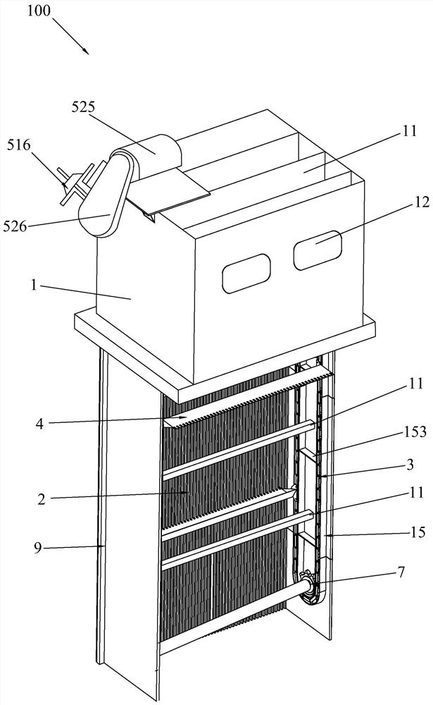
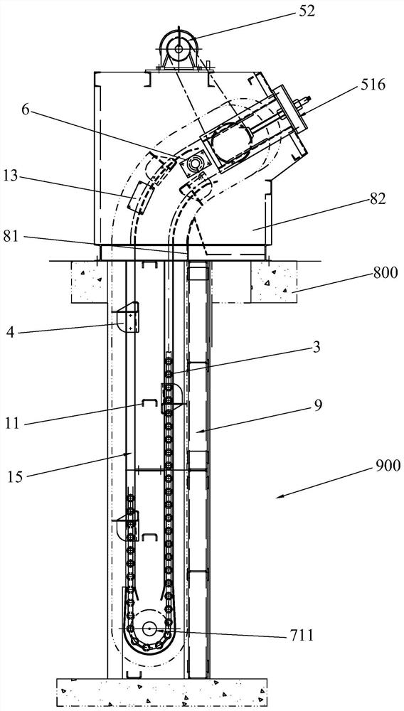
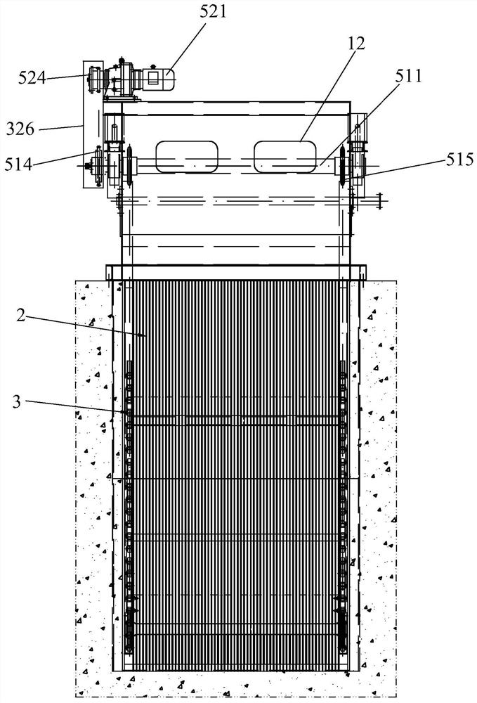
[0052] see Figure 1 to Figure 20 , the chain cleaning machine 100 of the present invention includes a frame 1, a grid 2, two traction chains 3, at least one cleaning bucket 4,...


PUM


Abstract

The invention discloses a chain cleaning machine, which comprises a frame, a grid, two traction chains, at least one cleaning rake bucket, a driving mechanism and a washing and unloading device. The grid is installed on the frame and vertically It is directly intercepted at the water channel, and the two traction chains are respectively installed on the opposite sides of the frame, and the two ends of the cleaning rake bucket are respectively fixed on the two traction chains. The dirt baffle plate is provided with a number of overflow grooves arranged horizontally and penetrating front and rear on the back dirt baffle plate, and the drive mechanism is installed on the frame, and the drive mechanism is used to drive the two traction chains to move to Drive the cleaning rake installed on the two traction chains to move to catch the dirt intercepted by the grid, the flushing and unloading device is installed on the frame, when the cleaning rake is located When the sewage is in the unloading position, the flushing and unloading device flushes the cleaning rake bucket through the plurality of overflow grooves on the rear dirt baffle.

Description

technical field [0001] The invention relates to the technical field of cleaning machines, in particular to a chain cleaning machine. Background technique [0002] According to the statistics of the Feedback Report on Important Events of Nuclear Power Operation in the World, since 2004, there have been more than 100 incidents related to the blockage of water intakes of nuclear power plants, of which nearly 80% of the incidents led to unit power reduction or shutdown, and more than 20% of the incidents were directly related to nuclear power plants. affect the security of the system. [0003] At present, the commonly used cleaning machine for the intake canal of nuclear power plants in China is a steel wire rope traction rake bucket cleaning machine, but this cleaning machine has the following disadvantages: First, this steel wire rope traction rake bucket cleaning machine has only one cleaning bucket. The cleaning rake bucket is pulled by the wire rope to complete the actions...

Claims


Application Information

Patent Timeline
Patent Type & Authority Patents(China)
IPC IPC(8): E02B15/10
CPCE02B15/10E02B15/104
Inventor 李德睿刘生根翁文庆李剑波张伟张波刘超罗卫华刘巍李超
Owner CHINA NUCLEAR POWER TECH RES INST CO LTD
Why Eureka
Try Eureka