AI technical title is built by Patsnap AI team. It summarizes the technical point description of the patent document.
A forming method and the technology of the annular cylinder, applied in the direction of the feeding device, positioning device, storage device, etc., can solve the problems of inability to accurately locate and realize automatic transfer, and achieve the effect of simplifying the processing process and improving production efficiency
Active Publication Date: 2021-04-27
长丰吾道智能光电科技有限公司
View PDF8 Cites 0 Cited by
Summary
Abstract
Description
Claims
Application Information
AI Technical Summary
This helps you quickly interpret patents by identifying the three key elements:
Problems solved by technology
Method used
Benefits of technology
Problems solved by technology
The defect of this forming method is that after the sheet is bent into an arc shape, it still has great flexibility because the two ends are not connected. During the transfer process, a slight shaking can deform it, so it cannot be processed Accurate positioning can not realize the automatic transfer of its processing process, which leads to the fact that the processing of such parts still needs to rely on a large number of manual operations at this stage
Method used
Image
Click on the blue label to locate the original text in one second.
Reading with bidirectional positioning of images and text.
Examples
Embodiment 1
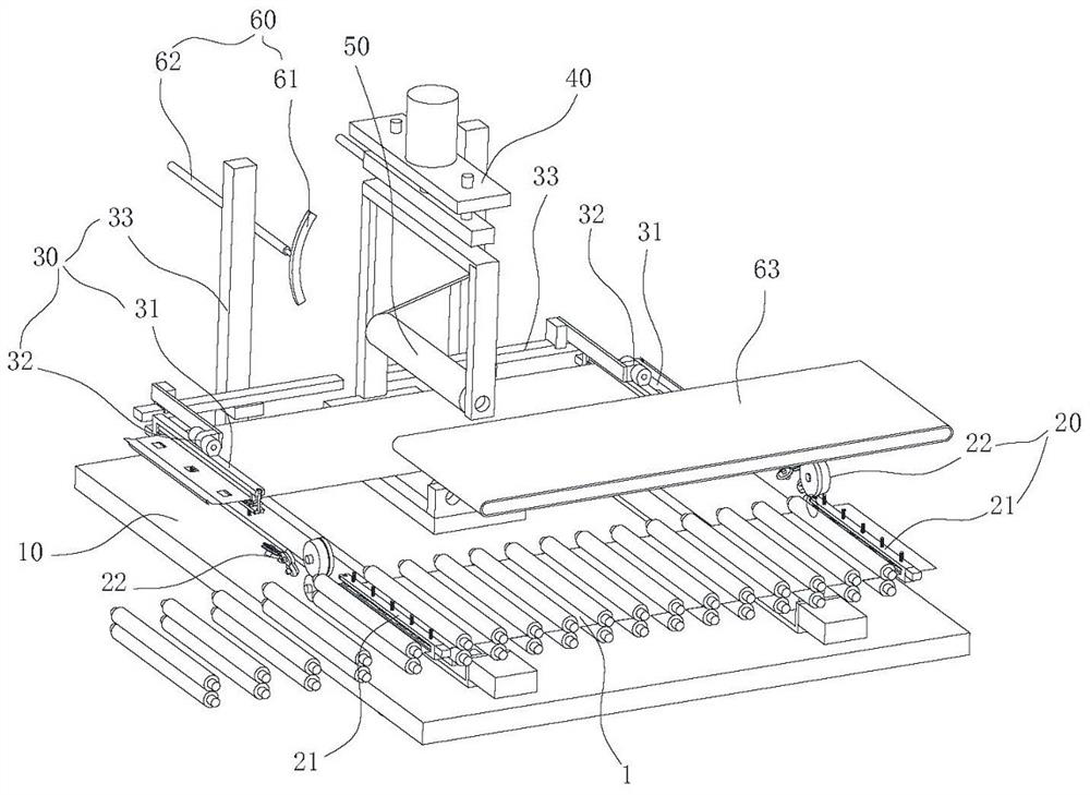
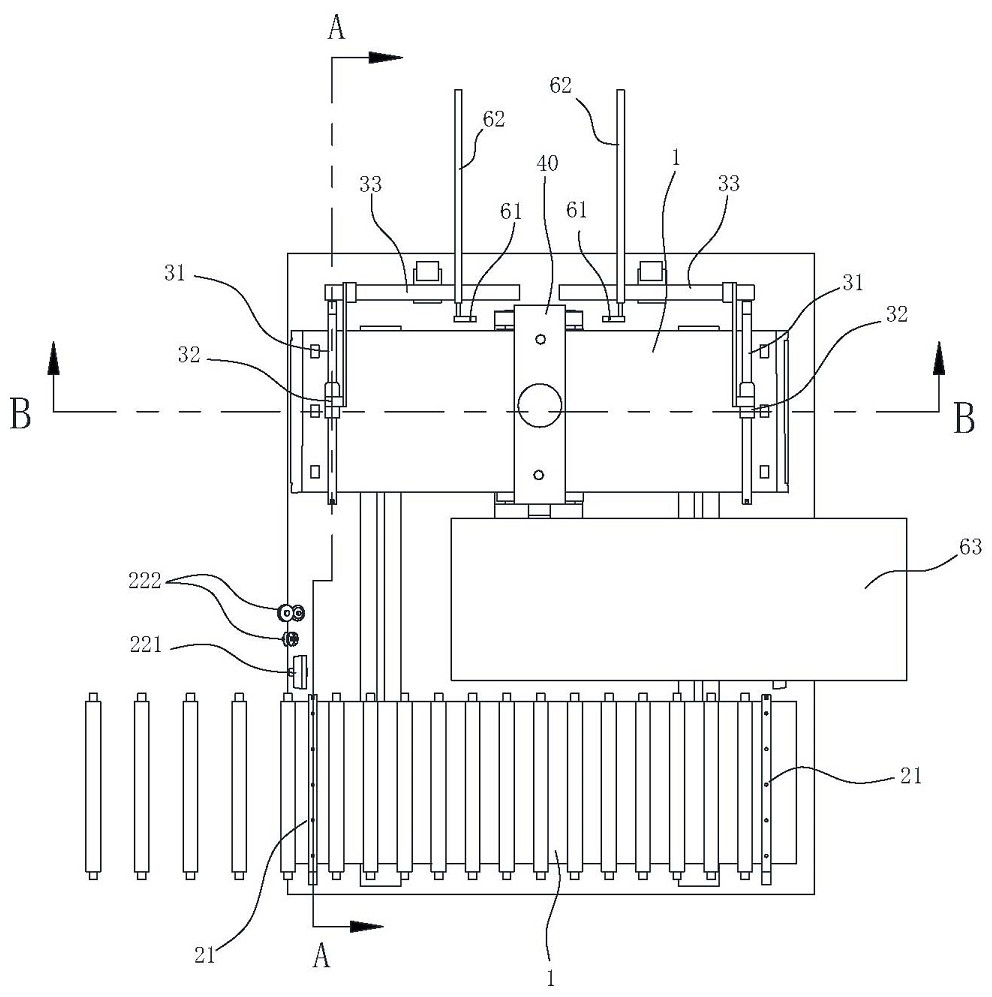
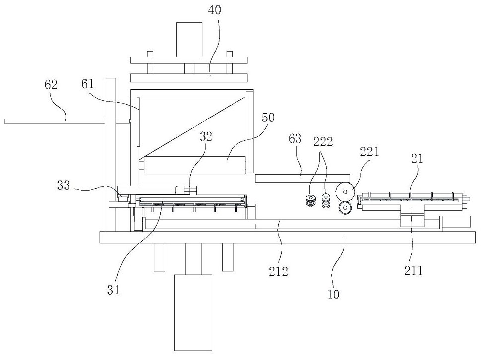
[0035]Such asfigure 1 ,2As shown, a laundry machine inner cylinder wall molding machine, including a folding mechanism 20, a flip mechanism 30, a buckle mechanism 40, and a shaping mechanism 50, which is used to bend two ends of the plane sheet 1 The V-shaped card opening and conveys the planar sheet 1 to the flip mechanism 30, the inverting mechanism 30 for flipping the both ends of the planar sheet 1 by 180 °, respectively, and at the seam sewing mechanism 40. The snug seam mechanism 40 is configured to secure the sheet 1 on both ends of the plane to a ring cylinder 2, the shaping mechanism 50 for pressing the annular cylindrical material 2 to cylindrical shape. The present invention integrates the roller press and buckle mechanism 40 of the cylindrical member, and adjusts the processing order, that is, after the seam is shaped, it is solved the deficiencies that the thin-walled parts roller pressure is not allowed to achieve thin wall cylinders. The automation of the part of the ...
Embodiment 2
[0047]A cartridge forming method for applying the above-described molding machine, including the steps of:
[0048]Step 1: Upset, cut the metal strip into a rectangular planar sheet 1;
[0049]Step 2: Criminalize, the uneven structure and mounting holes are stamped on the planar sheet 1 according to the design requirements;
[0050]Step 3: Fold, transport the planar sheet 1 to the folding mechanism 20, and use the flanged mechanism 20 to bend the V-shaped bay at both ends of the plane sheet 1;
[0051]Step 4: Turning, conveying the plane of the folded plane to the flip mechanism 30, using the flip mechanism 30 to flush 180 ° on both ends of the plane sheet 1, and transfer the V-shaped bay port of the end to the snug seam mechanism 40 Attack;
[0052]Step 5: Sewing, using the snug seam mechanism 40 to riveting the fastener area of the V-shaped bay, so that the plane sheet 1 is fixed to form a ring cylinder 2;
[0053]Step 6: Shape, release the flip mechanism 30, while clamping the ring cylinder 2 by...
PUM
Abstract
The invention belongs to the technical field of assembly and manufacturing, and in particular relates to a method for forming a cylindrical material, comprising the following steps: cutting a metal strip into rectangular flat sheets; Structure and mounting holes; hemming, using the hemming mechanism to bend the two ends of the flat sheet to form a V-shaped bayonet; flipping, using the flipping mechanism to turn the two ends of the flat sheet 180°, and make the V-shaped bayonet at both ends. Transfer to the buttoning mechanism for fastening; buttoning, using the buttoning mechanism to riveting and pressing the buckled area of the V-shaped bayonet; shaping, driving the shaping roller to rotate to make the ring-shaped cylinder rotate at least 360°; unloading, after shaping The cylindrical material is removed from the shaping mechanism, and the forming of the cylindrical material is completed. The cylindrical material of the invention adjusts the processing sequence, that is, first sewing and then shaping, which solves the defect that the thin-walled parts are not suitable for transportation after rolling, realizes the automatic forming of the thin-walled cylindrical parts, simplifies the processing process, and improves the production efficiency. .
Description
Technical field[0001]The present invention belongs to the field of home appliance manufacturing technology, and more particularly to a cylinder forming method.Background technique[0002]Such as the wall of the washing machine, the thin-walled cylindrical fitting generally uses the process sequential sequence of the first depression after the manufacturing process, that is, first press the planar tula roller out of the arc, and then riveting both ends of the plane sheet. Press into one. The defect in this forming method is that after the sheet is bent into an arc, since both ends are not connected, there is still a large flexibility. During the transfer process, slight shakes can be deformed, so it cannot be carried out Precisely positioning, it is also unable to achieve automated transport of its processing, which leads to the processing of such parts, still needs to rely on a lot of manual operation.Inventive content[0003]It is an object of the present invention to provide a cartrid...
Claims
Application Information
Patent Timeline
Application Date:The date an application was filed.
Publication Date:The date a patent or application was officially published.
First Publication Date:The earliest publication date of a patent with the same application number.
Issue Date:Publication date of the patent grant document.
PCT Entry Date:The Entry date of PCT National Phase.
Estimated Expiry Date:The statutory expiry date of a patent right according to the Patent Law, and it is the longest term of protection that the patent right can achieve without the termination of the patent right due to other reasons(Term extension factor has been taken into account ).
Invalid Date:Actual expiry date is based on effective date or publication date of legal transaction data of invalid patent.

