An easy-to-operate component pin bending device

A bending device and component technology, applied in the field of component pin bending, can solve the problems of unreachable use, cumbersome operation procedures, and different bending degrees, and achieve the effect of consistent curvature

Active Publication Date: 2021-03-26
湖南鑫铮科技有限公司
View PDF6 Cites 1 Cited by
  • Summary
  • Abstract
  • Description
  • Claims
  • Application Information

AI Technical Summary

Problems solved by technology

[0004] In order to overcome the fact that the existing manual bending of component pins is time-consuming and labor-intensive, and it is easy to hurt the hands, and the bending degree is different and cannot meet the requirements of use. When the existing pin bending mechanism bends the component pins, it needs to be divided into steps For bending, the bending cannot be completed at one time, and the operating procedures are cumbersome. The technical problem of the present invention is to provide an easy-to-operate component pin bending device with high bending efficiency and consistent bending degree.

Method used


Image

  • An easy-to-operate component pin bending device
  • An easy-to-operate component pin bending device
  • An easy-to-operate component pin bending device

Examples


Embodiment 1

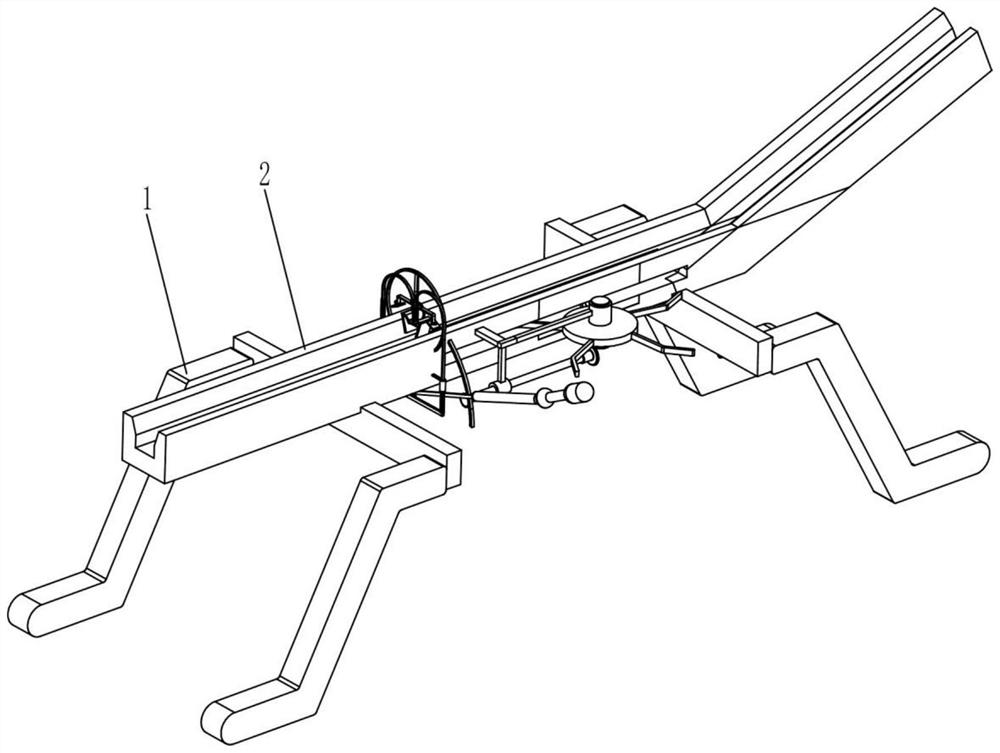
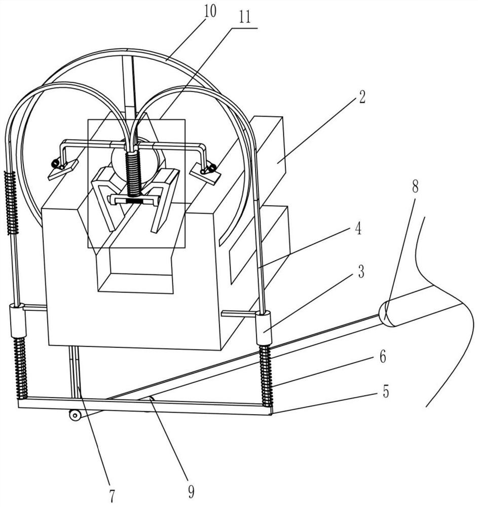
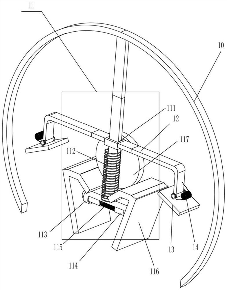
[0019] An easy-to-operate component pin bending device, as shown in 1-3, includes a fixed frame 1, and the upper ends of several fixed frames 1 for supporting functions are fixed by bolts and provided with slide plates 2 for sliding component pins , specifically six fixed frames 1, the outer side of the slide plate 2 is fixedly provided with an arc-shaped support plate 10 and two sliding sleeves 3 are symmetrically installed, and the front side of the arc-shaped support plate 10 is provided with an extruding part 11, The two sliding sleeves 3 are provided with moving rods 4, and the lower ends of the two moving rods 4 are connected by a connecting plate 5, and the upper ends of the two moving rods 4 are fixedly connected and connected with the extruding part 11. A vertical arm 7 is arranged on the outer bottom side of the slide plate 2, and the lower end of the vertical arm 7 is connected to a swing arm 8 through a rotating column. The roller 9 in contact with the bottom side,...

Embodiment 2

[0021] An easy-to-operate component pin bending device, as shown in 1-4, includes a fixed frame 1, and the upper ends of several fixed frames 1 for supporting functions are fixed by bolts and provided with slide plates for component pins to slide 2. Specifically, there are four fixed frames 1. The outer surface of the slide plate 2 is fixedly equipped with an arc-shaped support plate 10 and two sliding sleeves 3 for guiding functions are symmetrically installed. The front side of the arc-shaped support plate 10 is set There is an extruding part 11 for bending, and the two sliding sleeves 3 are provided with a moving rod 4 that can move up and down, and the lower ends of the two moving rods 4 are connected by a connecting plate 5, and the two moving rods 4 The upper ends are fixedly connected and connected with the extruding part 11, a vertical arm 7 is arranged on the bottom side outside the slide plate 2, and the lower end of the vertical arm 7 is connected to a swing arm 8 in...


PUM


Abstract

The invention relates to the technical field of component pin bending, in particular to a component pin bending device convenient to operate. The invention aims to provide a component pin bending device which is high in bending efficiency, consistent in bending degree and convenient to operate. The component pin bending device convenient to operate comprises fixed frames, a sliding plate, slidingsleeves and the like. The sliding plate is fixedly arranged on the fixing frames. An arc-shaped supporting plate and two symmetrically-installed sliding sleeves are arranged on the outer side surfaceof the sliding plate. An extrusion component is arranged on one side surface of the arc-shaped supporting plate. When a swing arm is held by a hand to swing downwards, a connecting rod and a flattening block are driven to move downwards so as to press the bent part of the pin upper end part of a component pin positioned below the flattening block to be in a horizontal state. The pin bending operation of the component is finished at a time conveniently and rapidly, and the bending curvatures of all the pins of the component are consistent.

Description

technical field [0001] The invention relates to the technical field of component pin bending, in particular to an easy-to-operate component pin bending device. Background technique [0002] Electronic components are components of electronic components and small electrical machines and instruments. They are often composed of several parts and can be used in similar products; they often refer to certain parts in industries such as electrical appliances, radios, and instruments, such as capacitors and transistors. The general term for sub-devices such as springs, hairsprings, and springs. [0003] At present, after the production process of components, some components still need to bend the pins before they can be used and applied. The existing manual bending of component pins is time-consuming and labor-intensive, and it is easy to hurt the hands. The bending degree is different and cannot be used. When the existing pin bending mechanism bends the component pins, it needs to ...

Claims


Application Information

Patent Timeline
Patent Type & Authority Patents(China)
IPC IPC(8): B21F1/00
CPCB21F1/00
Inventor 刘江南
Owner 湖南鑫铮科技有限公司
Why Eureka
Try Eureka