Bending machine

A bending machine and frame technology, applied in the field of bending machines, can solve the problems of high cost, low production efficiency, time-consuming and laborious, etc., and achieve the effect of low cost, high production efficiency and good bending effect

Inactive Publication Date: 2012-11-14
DELIX SUZHOU AUTOMATION MACHINE & TOOL
View PDF11 Cites 9 Cited by
  • Summary
  • Abstract
  • Description
  • Claims
  • Application Information

AI Technical Summary

Problems solved by technology

However, during the bending process of the terminal, springback will occur, so a two-stop bending method is required, and this bending method is time-consuming, laborious, low in production efficiency, and high in cost during the production process.

Method used


Image

  • Bending machine
  • Bending machine
  • Bending machine

Examples


Embodiment Construction

[0026] The following descriptions are only preferred embodiments of the present invention, and therefore do not limit the protection scope of the present invention.

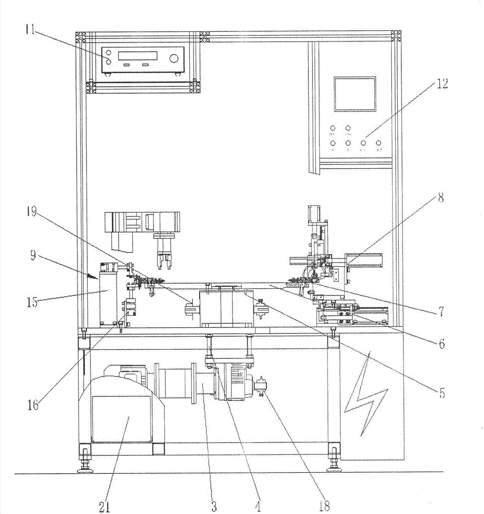
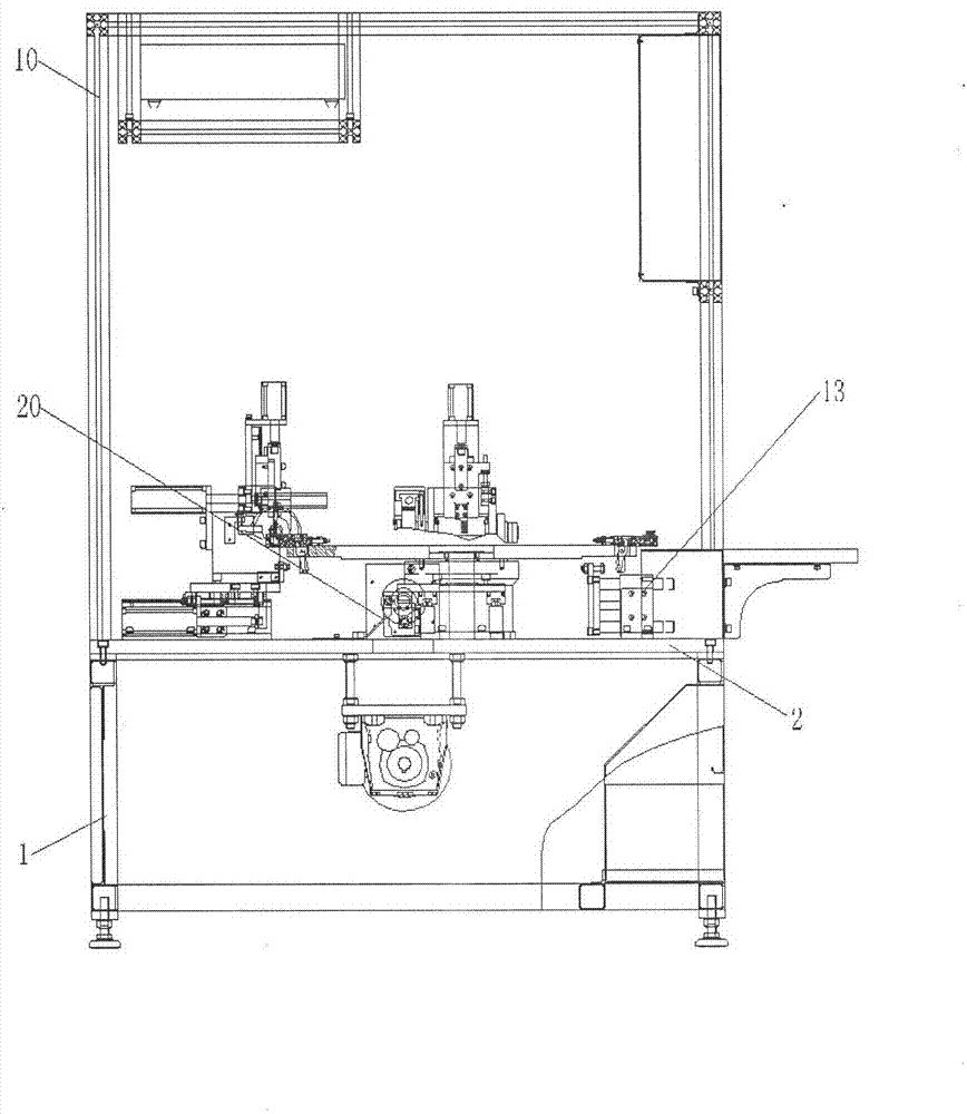
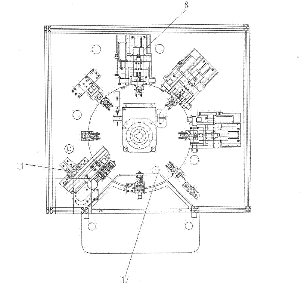
[0027] Such as Figure 1 to Figure 3 Shown: a bending machine, including a frame 1, the upper end of the frame 1 is provided with a platen 2, the middle part of the platen 2 is provided with a motor reducer 3, and the output end of the motor reducer 3 is connected with a chain tension wire The rod 4 and the chain tensioning screw 4 are connected with a splitter 5, the upper end of the splitter 5 is provided with a turntable 6, the upper end of the turntable 6 is evenly distributed with a clamp assembly 7, and the outer periphery of the turntable 6 is provided with a bending assembly 8 and a probe assembly 9, The outer edge of the table 2 is provided with a pressure tester 11 and a control box 12 passing through the upper enclosure structure 10, and a clamp opening cylinder assembly 13 for driving the clamp assemb...


PUM


Abstract

The invention relates to the technical field of hoisting devices, in particular to a bending machine which comprises a rack, wherein a platen is arranged at the upper end of the rack, a motor reducing gear is arranged in the middle of the platen, the output end of the motor reducing gear is connected with a chain tensioning lead screw, the chain tensioning lead screw is connected with a divider, a turntable is arranged at the upper end of the divider, clamp assemblies are evenly distributed at the upper end of the turntable, a bending assembly and a probe assembly are arranged on the outer periphery of the turntable, and a withstand voltage tester and a control box which pass through an upper enclosure structure are arranged at the outer edge of the platen. When the bending machine is used, the control box controls the clamp assemblies to clamp workpieces, the motor reducing gear drives the turntable, the clamp assemblies rotate to the bending assembly to perform bending processing for the workpieces, after bending processing, the motor reducing gear drives the turntable to rotate to be below a blanking mechanical arm assembly to demount the bent workpieces, and the operation is cycled. Therefore, the bending machine has the advantages of being good in one-time bending effect, high in production efficiency, time-saving, labor-saving and low in cost.

Description

technical field [0001] The invention relates to the technical field of terminal bending equipment, in particular to a bending machine. Background technique [0002] Generally, after the stamping is completed, the terminal is straight and not bent, so it cannot be directly applied to the connector, and it needs to be bent to a certain angle. However, in the prior art, in order to facilitate the receiving of the material without damaging the bending size, the terminal is received in a flat manner when receiving the material, and finally it is bent to a suitable angle with a bending tool. However, during the bending process of the terminal, there will be a springback phenomenon, so a two-stop bending method is required, and this bending method is time-consuming and laborious in the production process, with low production efficiency and high cost. Contents of the invention [0003] In view of the deficiencies in the above-mentioned prior art, the object of the present inventi...

Claims


Application Information

Patent Timeline
Patent Type & Authority Applications(China)
IPC IPC(8): B21F1/00
Inventor 魏连清吴海清李廷宇
Owner DELIX SUZHOU AUTOMATION MACHINE & TOOL
Why Eureka
Try Eureka