Eureka AIR delivers breakthrough ideas for toughest innovation challenges, trusted by R&D personnel around the world.

Road leveling device

A technology of leveling device and highway, applied in the direction of road, road, road repair, etc., can solve the problems of small leveling range, lack of guiding structure of leveling device, damage of pressing roller, etc., so as to improve leveling quality and improve leveling. quality effect

Active Publication Date: 2021-10-01
CHANGSHA UNIVERSITY OF SCIENCE AND TECHNOLOGY
View PDF6 Cites 1 Cited by
  • Summary
  • Abstract
  • Description
  • Claims
  • Application Information

AI Technical Summary

Problems solved by technology

The existing common pavement leveling equipment is a road roller. The road roller compacts and levels the road surface through the pressure of the rollers. The road roller can roll sandy, sticky soil, subgrade stabilized soil and asphalt concrete pavement layer. There is no road condition detection device when working. When it is applied to the road with serious bumps or pits, the pressure of the pressure roller cannot be adjusted, resulting in poor road leveling effect and damage to the pressure roller, which will affect the final road surface quality.
[0003] In actual use, there are the following problems: 1. The leveling device of the prior art road roller has a small leveling range and can only rely on the movement of the vehicle to adjust the leveling position
[0004] 2. Even if there is an adjustment device for the leveling device in the existing technology, the horizontal adjustment device is often installed below the vertical leveling mechanism, and it is difficult to obtain a large stroke leveling force
[0005] 3. The leveling device of the prior art road roller lacks a guiding structure, and the leveling device is prone to skew after working on uneven roads for a long time
[0006] 4. In the leveling device of the existing technology, the leveling plate is often adapted to the hydraulic rod or electric rod of the conventional specification. However, the problem caused by the use of the conventional specification is that it cannot be leveled with a large size
[0007] 5. The road rollers in the prior art may have sensors, but they lack a sensor device for real-time detection of the leveling distance

Method used


Image

  • Road leveling device
  • Road leveling device
  • Road leveling device

Examples


Embodiment Construction

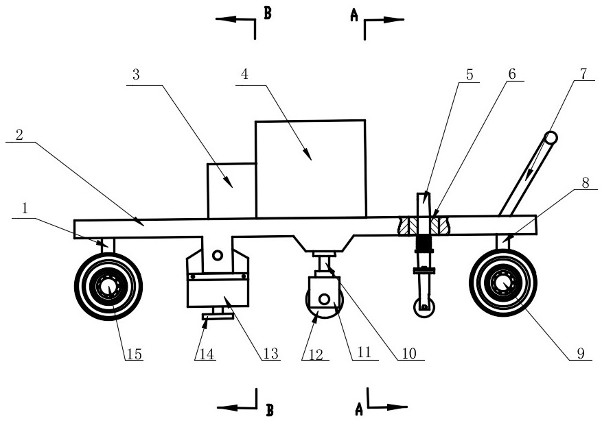
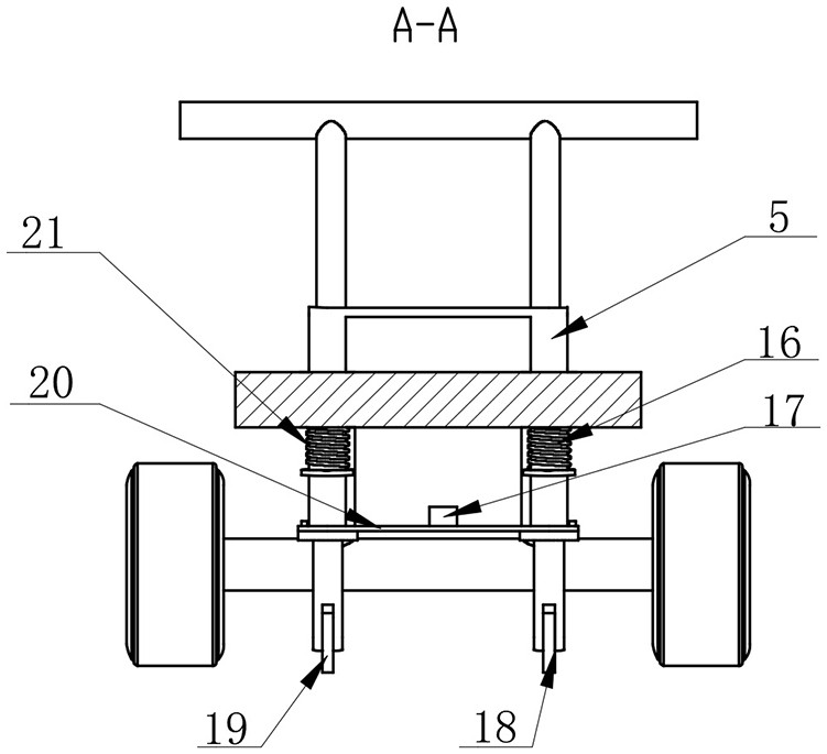
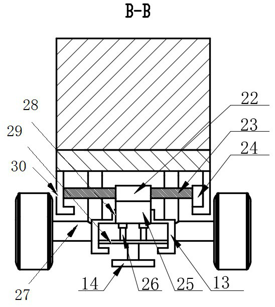
[0028] The structure and working principle of specific embodiments of the present invention will be further described in detail below in conjunction with the accompanying drawings.

[0029] Invention point of the present invention realizes and solves technical problem by following module:

[0030] 1. For the first point of the background technology, a multi-degree-of-freedom linkage method is adopted to realize fine adjustment of the leveling position.

[0031] 2. For the second point of the background technology, the design sequence of the horizontal adjustment mechanism at the top and the vertical leveling structure at the bottom is adopted to obtain a large stroke of the leveling plate and the piston plate, thereby obtaining good leveling force.

[0032] 3. For the third point of the background technology, the technology of piston cylinder guidance is adopted, and the connection between the folded edge and the motor box is used to make the alignment and guidance better.

...


PUM


Abstract

The invention provides a highway pavement leveling device, which belongs to the technical field of highway construction road surface leveling, and solves the problem that the existing road roller device has a poor leveling effect on uneven road surfaces. The distance between the vehicle floor is used to observe the degree of unevenness of the road surface to adjust the pressure of the pressure roller on the road surface in real time to improve the leveling quality of the road surface. In addition, an auxiliary leveling structure is designed to further improve the leveling quality of the road surface. This device has a simple structure and is practical. Strong, can greatly improve the leveling quality of the road surface.

Description

technical field [0001] The invention belongs to the technical field of road surface leveling for road construction, and in particular relates to a road surface leveling device. The road surface leveling device involved in the present invention has the functions of detecting the unevenness of the road surface and adjusting the height and pressure of the pressure roller in real time according to the unevenness of the road surface, so as to improve the road surface leveling quality and the service life of the pressure roller. It is suitable for construction occasions that require high road surface quality. Background technique [0002] The leveling and compaction of the road surface is an extremely important link in the field of road construction, and the leveling of the road surface determines the final quality and life of the road. The existing common pavement leveling equipment is a road roller. The road roller compacts and levels the road surface through the pressure of th...

Claims


Application Information

Patent Timeline
Patent Type & Authority Patents(China)
IPC IPC(8): E01C23/01E01C19/22E01C19/23
CPCE01C19/22E01C19/23E01C23/01
Inventor 黄浩杜荣华傅逸轩付玲黄毅何志勇
Owner CHANGSHA UNIVERSITY OF SCIENCE AND TECHNOLOGY
Why Eureka
Eureka Blog
Learn More