Vehicular headlamp

A technology for lamps and vehicles, which is applied in the direction of headlights, road vehicles, vehicle parts, etc., can solve the problem of increasing the number of parts, and achieve the effect of increasing the size and realizing the number of parts

Active Publication Date: 2020-04-03
KOITO MFG CO LTD
View PDF5 Cites 0 Cited by
  • Summary
  • Abstract
  • Description
  • Claims
  • Application Information

AI Technical Summary

Problems solved by technology

In this case, it is conceivable to use lenses and masks to align the spot diameter of the laser beam incident on the phase modulation element, but this will increase the number of parts

Method used


Image

  • Vehicular headlamp
  • Vehicular headlamp
  • Vehicular headlamp

Examples


no. 1 approach

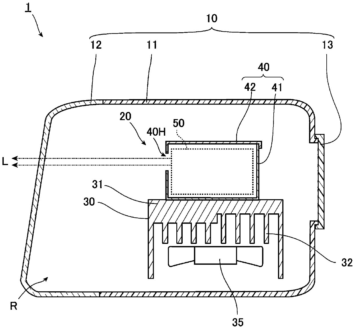
[0202] figure 1 It is a figure which shows an example of the vehicle lamp of this embodiment, and is a longitudinal cross-sectional view which shows typically the cross section of the up-down direction of the vehicle lamp. In this embodiment, the vehicle lamp is a vehicle headlamp 1. Such as figure 1 As shown, the vehicle headlamp 1 has a frame body 10 and a lamp unit 20 as main structures.

[0203] The frame body 10 has a lamp housing 11, a front cover 12, and a rear cover 13 as main structures. The lamp housing 11 has an opening at the front, and the front cover 12 is fixed to the lamp housing 11 in a manner of blocking the opening. In addition, an opening smaller than the front is formed in the rear of the lamp housing 11, and the rear cover 13 is fixed to the lamp housing 11 to close the opening.

[0204] The space formed by the lamp housing 11, the front cover 12 that closes the opening at the front of the lamp housing 11, and the rear cover 13 that closes the opening at the...

no. 2 approach

[0251] Next, a second embodiment of the present invention will be described. In addition, with regard to components that are the same or equivalent to those of the first embodiment, unless otherwise described, the same reference numerals are assigned and repeated descriptions are omitted.

[0252] Figure 7 With figure 2 Similarly, a diagram showing the lamp unit 20 of the vehicle headlamp 1 according to the second embodiment of the present invention. Such as Figure 7 As shown, the lamp unit 20 of the second embodiment is different from the lamp unit 20 of the first embodiment in that the light sources 52R, 52G, and 52B are mounted on the base 41 of the housing 40 via elastic members. Specifically, the first light source 52R is mounted on the base 41 via a pair of elastic members 157R, the second light source 52G is mounted on the base 41 via a pair of elastic members 157G, and the third light source 52B is mounted on the base 41 via a pair of elastic members 157B. 41. In add...

no. 3 approach

[0255] Next, a third embodiment of the present invention will be described. In addition, with regard to components that are the same or equivalent to those of the first embodiment, unless otherwise described, the same reference numerals are assigned and repeated descriptions are omitted.

[0256] Figure 8 With figure 2 Similarly, a diagram showing the lamp unit 20 of the vehicle headlamp 1 of the third embodiment of the present invention. In addition, in Figure 8 In order to facilitate understanding, a part of the housing 40 is omitted and shown. Such as Figure 8 As shown, in the lamp unit 20 of the third embodiment, the number of phase modulation elements of the optical system unit 50 is one, and three phase modulation elements 54R, 54G, and 54B are used to form the first and second optical system units 50 The lamp unit 20 of the second embodiment is different. Hereinafter, the structure of the lamp unit 20 of the third embodiment will be described.

[0257] In this embodim...


PUM


Abstract

An object of the present invention is to provide a vehicular headlamp that easily obtains a desired light distribution pattern. This vehicular headlamp (1) is provided with: light sources (52R, 52G, 52B); and a phase-modulation element assembly (54) comprising phase-modulation elements (54R, 54G, 54B) having multiple modulation parts (MPR, MPG, MPB) for forming light beams (LR, LG, LB) from the light sources (52R, 52G, 52B) into a predetermined light distribution pattern by diffracting the light beams (LR, LG, LB). A movable member (57R, 57G, 57B) moves the incident point of light of the phase-modulation elements (54R, 54G, 54B) relative to the phase modulation element (54R, 54G, 54B). The phase-modulation elements (54R, 54G, 54B) are divided into modulation sections (MP) that form the light distribution pattern. At least one modulation section (MP) is included in the incident point.

Description

Technical field [0001] The present invention relates to lamps for vehicles. Background technique [0002] Regarding vehicle headlights, which are vehicle lamps typified by automotive headlights, various structures that can make the emitted light have a desired light distribution pattern are discussed. For example, Patent Document 1 below describes that a holographic element, which is a type of phase modulation element, is used to form a predetermined light distribution pattern. [0003] In vehicle lamps represented by automobile headlights, various structures have been explored in order to make the light distribution pattern of the emitted light a predetermined light distribution pattern. For example, in Patent Document 1 described below, a holographic element, which is a kind of phase modulation element, is used to form a predetermined light distribution pattern. [0004] The vehicle lamp described in Patent Document 1 below has a hologram element and a light source that irradiate...

Claims


Application Information

Patent Timeline
IPC IPC(8): F21S41/141F21S41/20F21W102/10F21W107/10F21Y115/10
CPCF21S41/20F21W2102/10F21W2107/10F21S41/16F21Y2115/30F21S41/141F21S41/64B60Q1/14F21S45/10
Inventor 鬼头壮宜本桥和也
Owner KOITO MFG CO LTD
Why Eureka
Try Eureka