Image forming apparatus

An image and orthogonal direction technology, which is applied in the field of image forming devices, can solve the problems that the number of parts cannot be reduced and the degree of miniaturization is limited, and achieve the effect of reducing miniaturization, realizing the number of parts, and improving air flow

Active Publication Date: 2015-07-01
BROTHER KOGYO KK
View PDF5 Cites 0 Cited by
  • Summary
  • Abstract
  • Description
  • Claims
  • Application Information

AI Technical Summary

Problems solved by technology

[0007] However, since the image forming apparatus described in Patent Document 1 has ducts for cooling the circuit board, the number of parts cannot be reduced, and since a space for arranging the ducts must be secured in the main body of the device, the degree of miniaturization is limited.

Method used


Image

  • Image forming apparatus
  • Image forming apparatus
  • Image forming apparatus

Examples


Embodiment Construction

[0068] 1. The overall structure of the printer

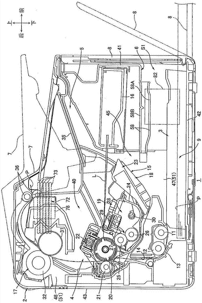
[0069] Such as figure 1 As shown, a printer 1 as an example of an image forming apparatus has a main body casing 2 as an example of a housing.

[0070] The main body case 2 is substantially box-shaped, and accommodates a paper feeder 3 configured to feed paper P as an example of a recording medium, and an image forming unit 4 configured to form an image on the supplied paper. on the paper P.

[0071] In addition, in the following description, when referring to the direction, the state of the printer 1 placed in the horizontal direction is taken as the reference, specifically, the figure 1 The right side of the paper is the front, with figure 1 The left side of the paper is the rear. In addition, when viewing the printer 1 from the front as a left-right basis, figure 1 The front of the paper is on the left, and the depth of the paper is on the right. in addition, figure 1 The top of the paper is the top, and the bottom of ...


PUM


Abstract

An image forming apparatus includes a main casing having side wall and a frame defining a sheet opening. The side wall of the main casing and the frame define an accommodating space therebetween. The frame defines a first vent, and the frame further defines a second vent disposed below the first vent closer to the side wall than the first vent

Description

technical field [0001] The present invention relates to an image forming apparatus using electrophotography. Background technique [0002] Conventionally, there is known an image forming apparatus including: an apparatus body having a housing structure; an image forming unit housed in the apparatus body; and a circuit board on which electric components are mounted and supplies power to the image forming unit. [0003] However, since the electrical components generate heat when the image forming apparatus operates, it is necessary to cool the electrical components to suppress temperature rise of the electrical components. [0004] Therefore, an image forming apparatus having a duct for cooling a circuit board on which electrical components are mounted has been proposed (for example, refer to Patent Document 1). In addition, the duct discharges the air heated by the electrical components of the circuit board to the outside of the device main body. [0005] Patent Document 1:...

Claims


Application Information

Patent Timeline
IPC IPC(8): G03G15/00G03G15/20G03G21/20
CPCG03G21/206G03G21/1619G03G21/20G03G15/2017
Inventor 冈本佳大
Owner BROTHER KOGYO KK
Why Eureka
Try Eureka