Spliced matrix display method and system

A matrix display and matrix technology, applied to TV system components, TV, color TV components, etc., can solve the problems of large delay and affect the real-time performance of splicing display, so as to reduce transmission delay and improve real-time performance Effect

Active Publication Date: 2020-04-03
GUANGZHOU LEAFUN CULTURE SCI & TECH
View PDF6 Cites 4 Cited by
  • Summary
  • Abstract
  • Description
  • Claims
  • Application Information

AI Technical Summary

Problems solved by technology

[0002] At present, most of the mosaic displays on the market are realized by video splitting matrix. In practice, it is found that when video splitting matrix is ​​used to realize mosaic display, if the resolution of the video signal source is large, the host that stores the video signal source will send the video signal source to the video There is usually a large delay when dividing the matrix, which affects the real-time performance of the splicing display

Method used


Image

  • Spliced matrix display method and system
  • Spliced matrix display method and system
  • Spliced matrix display method and system

Examples


Embodiment 1

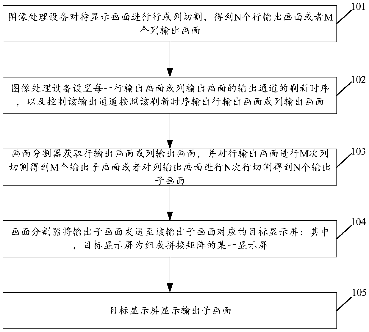
[0060] see figure 1 , figure 1 It is a schematic flowchart of a splicing matrix display method disclosed in the embodiment of the present application. The splicing matrix is ​​composed of N×M display screens, where N and M are integers greater than 1, such as figure 1 The shown mosaic matrix display method may specifically include the following steps:

[0061] 101. The image processing device divides the image to be displayed into rows or columns to obtain N row output images or M column output images.

[0062] In this embodiment of the application, the image processing device may include hardware devices such as computers, digital signal processing chips, and general-purpose or special-purpose software, and the image to be displayed may be a video image. Input into the computer, the video acquisition circuit and analog-to-digital conversion circuit in the computer convert the analog image signal into a digital image signal, and the digital image signal enters the digital si...

Embodiment 2

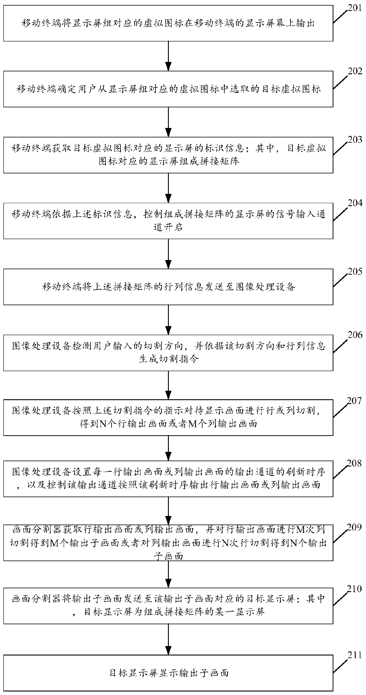
[0074] see figure 2 , figure 2 It is a schematic flowchart of another mosaic matrix display method disclosed in the embodiment of the present application. Among them, the display screens that make up the above-mentioned splicing matrix come from a display screen group, and the display screen group is composed of J×K display screens, wherein J and K are integers, and J≥N, K≥M, such as figure 2 The shown mosaic display method may specifically include the following steps:

[0075] 201. The mobile terminal outputs the virtual icon corresponding to the display group on the display screen of the mobile terminal.

[0076] In the embodiment of the present application, the mobile terminal may be the operating terminal of the system administrator of the mosaic matrix display system. In the embodiment of the present application, the mobile terminal may also perform the following steps before performing step 201:

[0077] The mobile terminal sends a matrix selection request carrying...

Embodiment 3

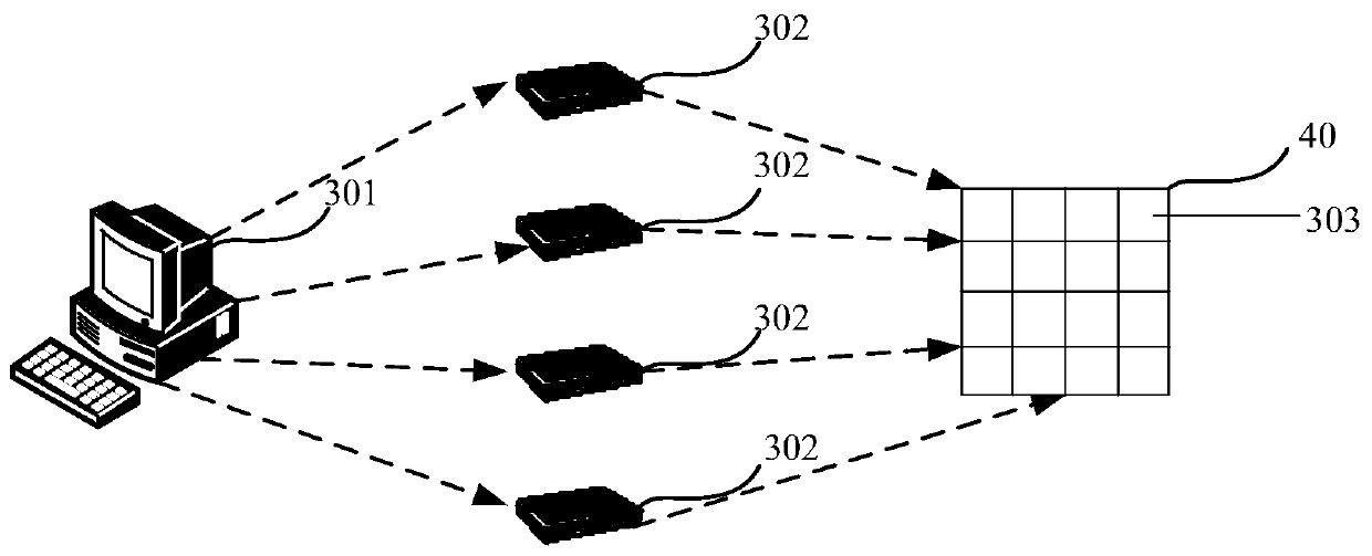
[0095] see image 3 , image 3 It is a structural schematic diagram of a mosaic matrix display system disclosed in the embodiment of this application. Wherein, the splicing matrix 40 in this application is composed of N×M display screens, wherein N and M are integers greater than 1, such as image 3 As shown, taking the mosaic matrix 40 as 4×4 as an example, the mosaic matrix display system may include:

[0096] The image processing device 301 is configured to perform row or column segmentation on the image to be displayed to obtain N row output images or M column output images, and set the refresh timing of the output channel of each row output image or column output image, and control the output The channel outputs a row output picture or a column output picture according to the refresh timing.

[0097] As an optional implementation manner, in the embodiment of the present application, the manner in which the image processing device 301 is used to set the refresh timing o...


PUM


Abstract

The embodiment of the invention discloses a spliced matrix display method and system. The method comprises the following steps: if a splicing matrix is composed of N * M display screens, the image processing equipment performing row or column cutting on the to-be-displayed image to obtain N row output images or M column output images, setting a refreshing time sequence of an output channel of eachrow output image or column output image, and controlling the output channel to output the row output images or column output images according to the set refreshing time sequence; the picture divideracquiring a row output picture or a column output picture, performing M times of column cutting on the row output picture to obtain M output sub-pictures or performs N times of row cutting on the column output picture to obtain N output sub-pictures, and sending the obtained output sub-pictures to a target display screen corresponding to the output sub-pictures; and the target display screen displaying the output sub-picture. By implementing the embodiment of the invention, the real-time performance of spliced display can be improved.

Description

technical field [0001] The present application relates to the technical field of mosaic display, in particular to a method and system for mosaic matrix display. Background technique [0002] At present, most of the mosaic displays on the market are realized by video splitting matrix. In practice, it is found that when video splitting matrix is ​​used to realize mosaic display, if the resolution of the video signal source is large, the host that stores the video signal source will send the video signal source to the video There is usually a large delay when dividing the matrix, which affects the real-time performance of the splicing display. Contents of the invention [0003] The embodiment of the present application discloses a mosaic matrix display method and system, which can improve the real-time performance of the mosaic display. [0004] The first aspect of the embodiment of the present application discloses a splicing matrix display method, the splicing matrix is ​​...

Claims


Application Information

Patent Timeline
Patent Type & Authority Applications(China)
IPC IPC(8): H04N5/262
CPCH04N5/262
Inventor 黄庆杰张国标
Owner GUANGZHOU LEAFUN CULTURE SCI & TECH
Why Eureka
Try Eureka