Circular steel plate plane milling and chamfering equipment

A face milling and steel plate technology, applied in other manufacturing equipment/tools, manufacturing tools, etc., can solve the problems of wasting manpower, time, trouble, etc., and achieve the effect of improving efficiency, convenient use and reducing time

Inactive Publication Date: 2020-04-07
PUJIANG JISHU MASCH TECH CO LTD
View PDF0 Cites 2 Cited by
  • Summary
  • Abstract
  • Description
  • Claims
  • Application Information

AI Technical Summary

Problems solved by technology

[0002] When the circular plate is produced, it is generally necessary to chamfer the corners. On the one hand, it is for aesthetics, and on the other hand, it will not protect the operator from being cut during installation or transfer. Traditional The plate processing generally needs to be milled first and then transferred to the chamfering equipment for chamfering, which is troublesome and wastes manpower and time

Method used


Image

  • Circular steel plate plane milling and chamfering equipment
  • Circular steel plate plane milling and chamfering equipment
  • Circular steel plate plane milling and chamfering equipment

Examples


Embodiment Construction

[0015] Combine below Figure 1-4 The present invention is described in detail, and for convenience of description, the orientations mentioned below are now stipulated as follows: figure 1 The up, down, left, right, front and back directions of the projection relationship itself are the same.

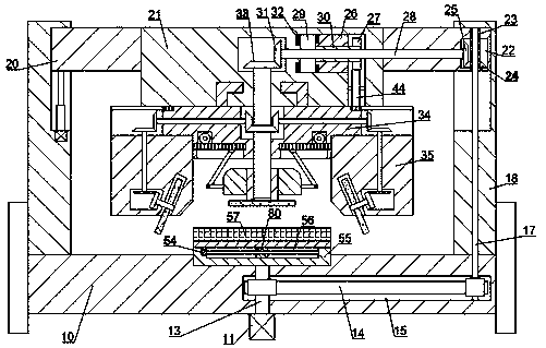
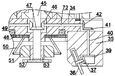
[0016] refer to Figure 1-4 According to an embodiment of the present invention, a round steel plate plane milling and chamfering equipment includes a base 10, two groups of left and right symmetrical columns 18 are fixed on the top surface of the base 10, and between the two groups of columns 18 A horizontal plate 20 is slidingly provided, and the horizontal plate 20 can move up and down under the control of the hydraulic pump. The top box 21 is fixed on the horizontal plate 20, and the bottom of the top box 21 is rotated to be provided with a rotating box 34. The left and right sides of the rotating box 34 are all slidably provided with a sliding box 35, the bottom of the rotating bo...


PUM


Abstract

The invention discloses circular steel plate plane milling and chamfering equipment. The equipment comprises a base. Two sets of stand columns which are symmetrical left and right are fixedly arrangedon the top face of the base. A transverse plate is arranged between the two sets of stand columns in a sliding mode. The transverse plate can move up and down under the control of a hydraulic pump; atop box is fixedly arranged on the transverse plate; a rotating box is rotationally arranged at the bottom of the top box; according to the invention, the corner milling function and the plane milling function are combined and are integrated into one equipment, so inconvenience caused by two equipment is greatly reduced, the step of transferring the steel plate to the chamfering equipment after plane milling is omitted, time is shortened, the sliding box can rotate, the rotary disc can drive the steel plate to rotate in the opposite direction, and the chamfering and milling efficiency is greatly improved.

Description

technical field [0001] The invention relates to the technical field of milling, in particular to a plane milling and chamfering equipment for circular steel plates. Background technique [0002] When the circular plate is produced, it is generally necessary to chamfer the corners. On the one hand, it is for aesthetics, and on the other hand, it will not protect the operator from being cut during installation or transfer. Traditional The processing of high-quality plates generally needs to be milled first and then transferred to the chamfering equipment for chamfering, which is troublesome and wastes manpower and time. Contents of the invention [0003] The object of the present invention is to provide a circular steel plate plane milling and chamfering equipment for overcoming the above-mentioned defects in the prior art. [0004] A plane milling and chamfering equipment for a circular steel plate according to the present invention comprises a base, two groups of left and...

Claims


Application Information

Patent Timeline
Patent Type & Authority Applications(China)
IPC IPC(8): B23P23/04
CPCB23P23/04
Inventor 不公告发明人
Owner PUJIANG JISHU MASCH TECH CO LTD
Why Eureka
Try Eureka