A crimping device for continuous film delivery

A crimping device and film technology, applied in the continuous transmission processing of films, film transmission machinery and equipment, can solve the problems of difficult film bonding and continuous transmission, complex bonding process, difficult film bonding processing, etc., to achieve improved automation Degree, continuous and smooth transmission, reasonable structure design effect

Active Publication Date: 2021-01-26
浙江耀阳新材料科技有限公司
View PDF4 Cites 0 Cited by
  • Summary
  • Abstract
  • Description
  • Claims
  • Application Information

AI Technical Summary

Problems solved by technology

During the production and processing process of the existing film, the film is unwound and conveyed along with the film. In order to ensure the continuity of the film conveying process, it is necessary to separate the tail end of the former film roll that has been unwound and the head end of the newly replaced film roll. For bonding, the bonding process between the existing two rolls of film is carried out manually. It is necessary to pull the end of the newly replaced film roll smoothly so that the ends of the two sides of the two rolls of film are overlapped and bonded. The existing The film bonding is manually operated, the operation efficiency of film bonding is low, it is difficult to achieve efficient and stable film bonding processing, the bonding process is complicated, and the time for bonding the ends of the film on both sides is long, resulting in the process of replacing the film roll Need to shut down the operation, which reduces the efficiency of film production and processing, and the bonding of the ends of both sides of the film is manually operated, the quality of film bonding is difficult to be guaranteed, and it is easy to produce skewed wrinkles during the bonding process of the film, and it is difficult to realize the film Smooth and accurate bonding and continuous transmission cannot meet the needs of production and processing

Method used


Image

  • A crimping device for continuous film delivery
  • A crimping device for continuous film delivery
  • A crimping device for continuous film delivery

Examples


Embodiment Construction

[0017] In order to further describe the present invention, a specific implementation of a crimping device for continuous film conveyance will be further described below in conjunction with the accompanying drawings. The following examples are explanations of the present invention and the present invention is not limited to the following examples.

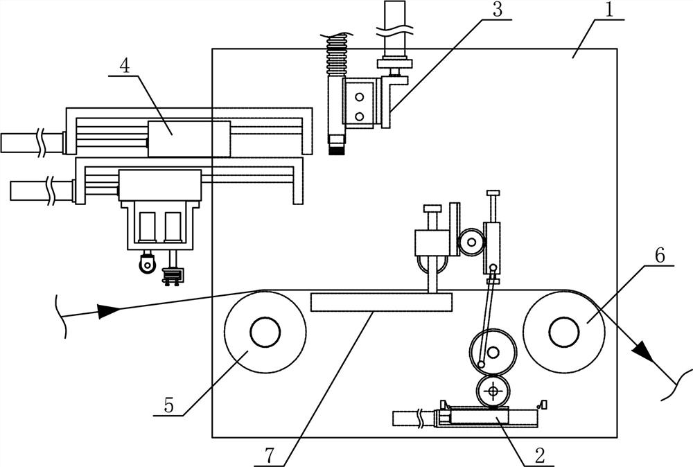
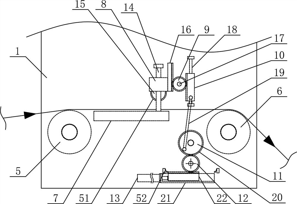
[0018] Such as figure 1 As shown, a crimping device for film continuous transmission in the present invention includes a film crimping support 1, a film pressing mechanism 2, a gluing mechanism 3 and a film pulling and crimping mechanism 4, and the two sides of the middle part of the film crimping support 1 are respectively The film feed guide roller 5 and the film discharge guide roller 6 are connected by horizontal rotation, and the film crimping support plate 7 is fixed horizontally on the film crimping bracket 1 between the film feed guide roller 5 and the film discharge guide roller 6, and the film is pulled and pressed. The bo...


PUM


Abstract

The invention discloses a crimping device for film continuous transmission, which belongs to the field of film transmission machinery. The invention includes a film crimping support, a film pressing mechanism, a gluing mechanism, and a film pulling and crimping mechanism. The two sides of the middle part of the film crimping support are horizontally connected with a film inlet guide roller and a film outlet guide roller, and a film inlet guide roller and an outlet roller. The film crimping support plate is fixed horizontally on the film crimping support between the film guide rollers, the film pulling and crimping mechanism is fixed horizontally on the film crimping support on the upper side of the film feeding guide roller, and the gluing mechanism is fixed horizontally on the film The film crimping bracket on the upper side of the crimping support plate, and the film pressing mechanism is horizontally arranged on one side of the film crimping support plate between the film inlet guide roller and the film outlet guide roller. The invention has a reasonable structural design, can quickly and efficiently crimp the ends of two rolls of film that are sequentially conveyed, realize smooth and smooth continuous conveyance of the film, improve the degree of automation of film conveyance, and meet the needs of production and use.

Description

technical field [0001] The invention belongs to the field of film conveying machinery and equipment, and in particular relates to a crimping device for continuous conveying of films, which is mainly used in the field of continuous conveying and processing of films. Background technique [0002] A film is a thin and soft transparent sheet, mainly made of plastic, adhesive, rubber or other materials. The scientific explanation of the film is: a two-dimensional material formed by depositing atoms, molecules or ions on the surface of the substrate. The film Material refers to a thin metal or organic layer with a thickness ranging from a single atom to a few millimeters. Thin films are widely used in electronics, machinery and printing industries, among which electronic semiconductor functional devices and optical coatings are the main applications of thin film technology. According to the classification of raw materials used, film materials can be divided into: polyethylene film...

Claims


Application Information

Patent Timeline
Patent Type & Authority Patents(China)
IPC IPC(8): B65H19/18B65H23/038B65H20/02
CPCB65H19/1805B65H20/02B65H23/038B65H2701/175
Inventor 胡罗江徐强张涛吴勇
Owner 浙江耀阳新材料科技有限公司
Why Eureka
Try Eureka