An entrance and exit control system and method meeting evacuation requirements

A control system, entrance and exit technology, applied in the direction of a single input port/output port register, instrument, time register, etc., can solve the problems of poor universality, pipeline exposure, high cost, improve safety protection ability, increase protection Ability, the effect of improving the protection ability

Active Publication Date: 2021-10-15
THE FIRST RES INST OF MIN OF PUBLIC SECURITY
View PDF0 Cites 0 Cited by
  • Summary
  • Abstract
  • Description
  • Claims
  • Application Information

AI Technical Summary

Problems solved by technology

In the application process of these two modes, there have always been two problems: one is the contradiction between the security protection requirements and the security evacuation requirements; the other is the security problem of the system itself
There are certain drawbacks in these several types of schemes, such as the outdoor safe escape passage is more difficult to meet the escape ability of some people (children, old people); poor fit
[0014] B. The security protection capability of the system itself is insufficient
[0015] During the construction of the system, it is difficult to centrally arrange all the pipelines in the controlled area, and there are cases where the pipelines are exposed in the uncontrolled area
If the application mode of "power-on lock, power-off open" is used, the forced opening can be realized by destroying the power cord of the electromagnetic lock, which reduces the safety protection ability of the entrance and exit
[0016] In addition, under the two application modes of "power-on lock, power-off open" and "power-off lock, power-on open", except for the door leaf hinge, the door leaf and the door frame have only one locking point, and there is also the problem of insufficient protection strength

Method used


Image

  • An entrance and exit control system and method meeting evacuation requirements
  • An entrance and exit control system and method meeting evacuation requirements
  • An entrance and exit control system and method meeting evacuation requirements

Examples


Embodiment 1

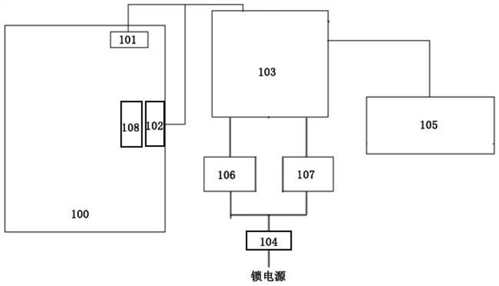
[0045] This embodiment provides an access control system that meets the evacuation requirements, such as figure 2 As shown, it includes a locking device 101 for turning on and off the electric lock, a locking device 102 for turning on and off the electric lock, an entrance and exit controller 103, and one or both of the reading device 106 and the requesting to leave device 107 The locking device 101 of the power-on lock and the power-off opening is installed on the door leaf and the door frame, forming a locking point of the door leaf and the door frame; the locking device 102 of the power-on-off electric lock is installed on the door frame, and installed on The oblique bolt mechanical lock 108 on the door leaf cooperates to form another locking point of the door leaf and the door frame; COM end and NC end) are connected to the lock power supply; the locking device 102 of the energized on-off electric lock is connected to the lock power supply through the normally open output...

Embodiment 2

[0053] This embodiment provides a method for utilizing the system described in Embodiment 1, including the following steps:

[0054] When the relay of the entrance and exit controller 103 is connected to the normally closed output contact of the locking device 101 when the power lock is powered off, the normally closed output contact of the locking device 102 connected to the power on and off electric lock is in the disconnected state. , the door leaf and door frame are locked;

[0055] When the entrance / exit controller 103 receives the information from the reading device 106 or the request to leave the device 107, it processes the information. If the authentication rule is passed, the relay in the entrance / exit controller 103 will act and link the lock device 101 with the power-on lock off and on. Simultaneously with the locking device 102 of the power on and off electric lock, the normally closed output contact of the locking device 101 connected to the power on lock changes...

Embodiment 3

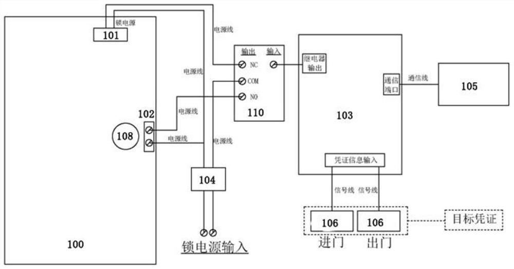
[0060] This embodiment is based on the system of embodiment 1 and the method of embodiment 2, and provides an example suitable for the door of the building body, such as image 3 shown.

[0061] In this embodiment, a locking device 101 (electromagnetic lock) with an electric lock and a power-off lock is installed on the door body and the door frame top of the entrance and exit, and a locking device 102 with a power-on and power-off electric lock is installed on the side of the door frame of the entrance and exit. (cathode lock), and the oblique tongue mechanical lock 108 that cooperates with the cathode lock work is installed on the corresponding position of the door leaf. The oblique bolt mechanical lock can only be opened with a key (i.e. a fixed handle) outside the door, and the control handle part (i.e. a movable handle) of the oblique bolt mechanical lock is installed on the inside of the door. Power is supplied to the electromagnetic lock and the cathode lock through th...


PUM


Abstract

The invention discloses an entrance and exit control system and method that meet evacuation requirements. The system includes a locking device for turning on and off the electric lock, a locking device for turning on and off the electric lock, an entrance and exit controller, a reading device and / or a request to leave device; the locking device for power-on lock and power-off is installed on the door leaf and the door frame, forming a locking point between the door leaf and the door frame; The mechanical lock cooperates to form another locking point of the door leaf and the door frame; the locking device of the power-on lock is connected to the lock power supply through the normally closed output contact of the relay of the entrance and exit controller; the locking device of the power-on and power-off electric lock The normally open output contact of the relay of the entrance / exit controller is connected to the power supply of the lock; the reading device and / or the device for requesting to leave is connected to the entrance / exit controller. The invention can improve the anti-technical opening ability of the entrance and exit, and can effectively improve the safety protection ability under the premise of meeting the requirements of safe evacuation.

Description

technical field [0001] The invention relates to the technical field of access control systems, in particular to an access control system and method meeting evacuation requirements. Background technique [0002] The entrance and exit control system, commonly known as the access control system, refers to the use of custom coded information identification and / or pattern feature information identification technology to control the opening and closing of the entrance and exit execution device, so as to implement the release, rejection, recording and warning of the entry and exit behavior of the target at the entrance and exit. operating electronic systems. The access control system is an integral part of the electronic protection system in the security system. The purpose of setting up the entrance and exit control system is to realize the "safety" of the entrance and exit. The "safety" of the entrance and exit control system needs to have social attributes and natural attribut...

Claims


Application Information

Patent Timeline
Patent Type & Authority Patents(China)
IPC IPC(8): G07C9/00G07C9/20G07C9/37
CPCG07C9/00571G07C9/00896G07C9/00944
Inventor 肖瑞林徐常星史彦林邢更力
Owner THE FIRST RES INST OF MIN OF PUBLIC SECURITY
Why Eureka
Try Eureka