LED display screen
A technology of LED display screen and LED array, which is applied in the direction of instruments, identification devices, etc., can solve the problems affecting the 3D display effect, and achieve the effects of avoiding mutual interference of light, increasing pixel filling rate, and eliminating graininess
- Summary
- Abstract
- Description
- Claims
- Application Information
AI Technical Summary
Problems solved by technology
Method used
Image

Examples
Embodiment 1
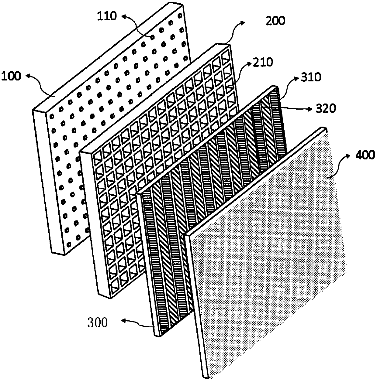
[0048] Figure 7 Is a cross-sectional view of the LED display screen in the first embodiment of the present invention; Figure 7 As shown, in this embodiment, the polarizer 300 is disposed between the diffuser film 400 and the matrix light-shielding frame 200, that is, the LED display screen includes an LED array 100, a matrix light-shielding frame 200, a polarizer 300 and Diffusion film 400. The LED light-emitting units 110 on the LED array 100 are arranged in the hollow grid 210 of the matrix light-shielding frame 200. In order to ensure that the LED display screen has a higher screen-to-body ratio, the LED light-emitting units 110 in the LED array 100 are connected to the driver The circuit 120 and the driving chip 130 are arranged on different sides of the substrate. The polarizer 300 may be Figure 4 to Figure 6 Any of the polarizers shown in.
[0049] In order to improve the degree of polarization and the polarization effect of the emitted light, in this embodiment, the di...
Embodiment 2
[0053] Picture 9 Is a cross-sectional view of the LED display screen in the second embodiment of the present invention; Picture 9 As shown, the difference between this embodiment and the first embodiment is that the polarizer 300 is arranged on the outside of the diffusion film 400 (the side away from the LED array 100), that is, the diffusion film 400 is arranged on the Between the polarizer 300 and the matrix light shielding frame 200. The polarizer 300 may be Figure 4 to Figure 6 Any of the polarizers shown in. The polarizer in this embodiment can also increase the degree of polarization of the emitted light. Compared with the first embodiment, the feature of this embodiment is that the light is non-polarized light before it is incident on the polarizer 300 (the diffusion film 400 does not change the polarization state of the light emitted by the LED), so that the polarizer emitted by the polarizer 300 is not polarized. Will be affected by the scattering of the diffusion...
Embodiment 3
[0057] Picture 10 Is a cross-sectional view of the LED display screen in the third embodiment of the present invention; Picture 10 As shown, the difference between this embodiment and the first embodiment is that the polarizer 300 is disposed between the LED array 100 and the matrix light-shielding frame 200. The polarizer 300 may be Figure 4 to Figure 6 Any of the polarizers shown in.
[0058] In order to eliminate the light crosstalk between adjacent LED light-emitting units 110 of the LED array 100, the LED array 100 further includes a light cover 140 arranged on the substrate, and the light cover 140 is provided with the same number of switches as the LED light-emitting units 110. Each LED light-emitting unit 110 is located at the center of an opening, and the height of the light cover is greater than or equal to the height of the LED light-emitting unit 110, so that the light emitted by the LED light-emitting unit 110 will not pass through the polarizer. Interfere with ea...
PUM
 Abstract
Description
Claims
Application Information
 - R&D
- Intellectual Property
- Life Sciences
- Materials
- Tech Scout
- Unparalleled Data Quality
- Higher Quality Content
- 60% Fewer Hallucinations
Browse by: Latest US Patents, China's latest patents, Technical Efficacy Thesaurus, Application Domain, Technology Topic, Popular Technical Reports.
© 2025 PatSnap. All rights reserved.Legal|Privacy policy|Modern Slavery Act Transparency Statement|Sitemap|About US| Contact US: help@patsnap.com