A material transfer device

A technology of transmission device and transmission unit, which is applied in the directions of transportation and packaging, conveyor objects, etc., can solve the problems of weak stability and poor synchronization, and achieve the effect of strong stability, good stability and reduced operation difficulty.

Active Publication Date: 2022-02-22
WUHAN DR LASER TECH CORP LTD
View PDF0 Cites 0 Cited by
  • Summary
  • Abstract
  • Description
  • Claims
  • Application Information

AI Technical Summary

Problems solved by technology

[0005] The purpose of the present invention is to overcome the defects and problems of poor synchronization and weak stability existing in the prior art, and provide a material distribution transmission device with good synchronization and strong stability

Method used


Image

  • A material transfer device
  • A material transfer device
  • A material transfer device

Examples


Embodiment 1

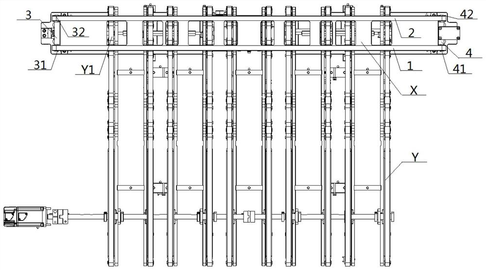
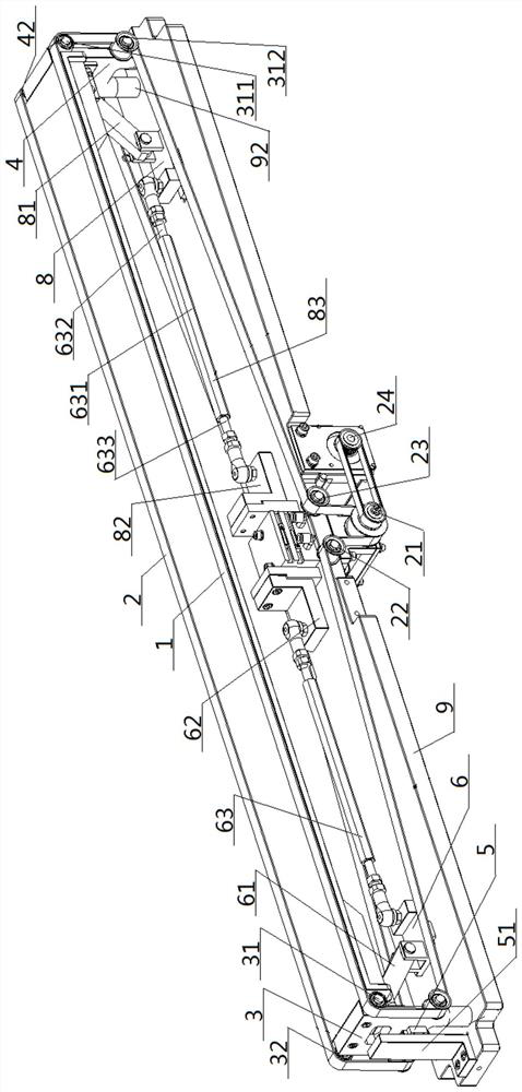
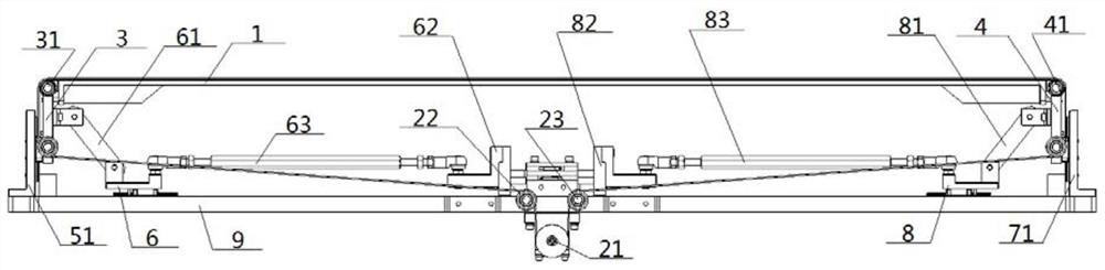
[0058] A material distribution transmission device, comprising a lifting transmission unit X and at least one piece transmission unit Y, the transmission direction of the lifting transmission unit X is different from the transmission direction of the piece transmission unit Y, and one end of the piece transmission unit Y Near the transmission surface of the lifting transmission unit X is set, the other end of the slice transmission unit Y is set away from the transmission surface of the lifting transmission unit X, and the transmission surface of the lifting transmission unit X includes a front conveyor belt 1 and a rear conveyor belt 2; The transmission unit X includes a front conveyor belt 1, a rear conveyor belt 2, a left support frame 3 and a right support frame 4, and the two ends of the front conveyor belt 1 are wound around the outer sides of the left front belt drive structure 31 and the right front belt drive structure 41 respectively. , the two ends of the rear convey...

Embodiment 2

[0064] Basic content is the same as embodiment 1, the difference is:

[0065] The left front belt driving structure 31 , the left rear belt driving structure 32 , the front belt driving structure and the right rear belt driving structure 42 are all upper rollers 311 and lower rollers 312 which are arranged up and down.

Embodiment 3

[0067] Basic content is the same as embodiment 1, the difference is:

[0068] The left horizontal drive mechanism 62 and the right horizontal drive mechanism 82 are any of the following:

[0069] The first type: the left horizontal drive mechanism 62 and the right horizontal drive mechanism 82 are each an air cylinder, motor or hydraulic cylinder;

[0070] The second type: the left horizontal drive mechanism 62 and the right horizontal drive mechanism 82 are the left and right output ends of the air gripper;

[0071] The third type: the left horizontal drive mechanism 62 and the right horizontal drive mechanism 82 are the left and right output ends of the double-rod cylinder.


PUM


Abstract

A material distribution transmission device, comprising a lifting transmission unit and at least one slice transmission unit, the transmission direction of the lift transmission unit is different from that of the slice transmission unit, and one end of the slice transmission unit is close to the lift transmission unit The transmission surface is set, and the other end of the sliced ​​transmission unit is set away from the transmission surface of the lifting transmission unit. The lifting transmission unit includes a front conveyor belt, a rear conveyor belt, a left support frame and a right support frame. The front conveyor belt and the rear conveyor belt are both For a telescopic conveyor belt, a longitudinal sliding structure is provided on the outer surfaces of the left and right support frames, and the inner surfaces of the left and right support frames are hinged with the top of an oblique link, and the bottom end of the oblique link is connected with a The horizontal sliding structure is connected. This design not only has good synchronization and strong stability, but also has strong labor-saving effect and easy adjustment of lifting height.

Description

technical field [0001] The invention relates to a transmission device, which belongs to the technical field of transmission, in particular to a material distribution transmission device. Background technique [0002] In the field of precision machining technology, in many application scenarios, it is necessary to lift the transmission device so that the materials conveyed on it can reach different heights, and then the materials can be transported to destinations of different heights. [0003] In the prior art, one or more cylinders are used to directly lift the transmission device. When multiple cylinders are used for jacking, it is difficult to ensure the synchronization of cylinder lifting, especially in long-distance transmission. It is difficult to ensure the level of the transmission device. There may even be an inclination, and an accident in which the position of the transmission target is shifted occurs, which affects the transmission accuracy. [0004] The disclos...

Claims


Application Information

Patent Timeline
Patent Type & Authority Patents(China)
IPC IPC(8): B65G47/52
CPCB65G47/52
Inventor 王佳辉卫哲黄海徐贵阳
Owner WUHAN DR LASER TECH CORP LTD
Why Eureka
Try Eureka