
Power head device, power head system and control method

A technology of a power head and an outer frame, which is applied to drilling equipment and methods, support devices, and earthwork drilling and mining, and can solve problems such as insufficient drill bit feed force and low construction efficiency, and achieve convenient and fast drilling, improved construction efficiency, and Flexible effects for applicable scenarios

Pending Publication Date: 2020-04-10
广东吉特高喷基础工程有限公司
View PDF0 Cites 0 Cited by
  • Summary
  • Abstract
  • Description
  • Claims
  • Application Information

AI Technical Summary

Problems solved by technology

[0005] An embodiment of the present invention provides a power head device, a power head system and a control method, which are used to solve the problems of insufficient feed force of the drill bit and low construction efficiency of the self-forming hole method

Method used


Image

  • Power head device, power head system and control method
  • Power head device, power head system and control method
  • Power head device, power head system and control method

Examples


Embodiment Construction

[0039] In order to make the technical problems, technical solutions and beneficial effects to be solved by the present invention clearer, the present invention will be further described in detail below in conjunction with the accompanying drawings and embodiments. It should be understood that the specific embodiments described here are only used to explain the present invention, not to limit the present invention.

[0040] It should be noted that when an element is referred to as being “fixed” or “disposed on” another element, it may be directly on the other element or be indirectly on the other element. When an element is referred to as being "connected to" another element, it can be directly connected to the other element or indirectly connected to the other element.

[0041]It is to be understood that the terms "length", "width", "top", "bottom", "front", "rear", "left", "right", "vertical", "horizontal", "top", The orientation or positional relationship indicated by "bott...


PUM


Abstract

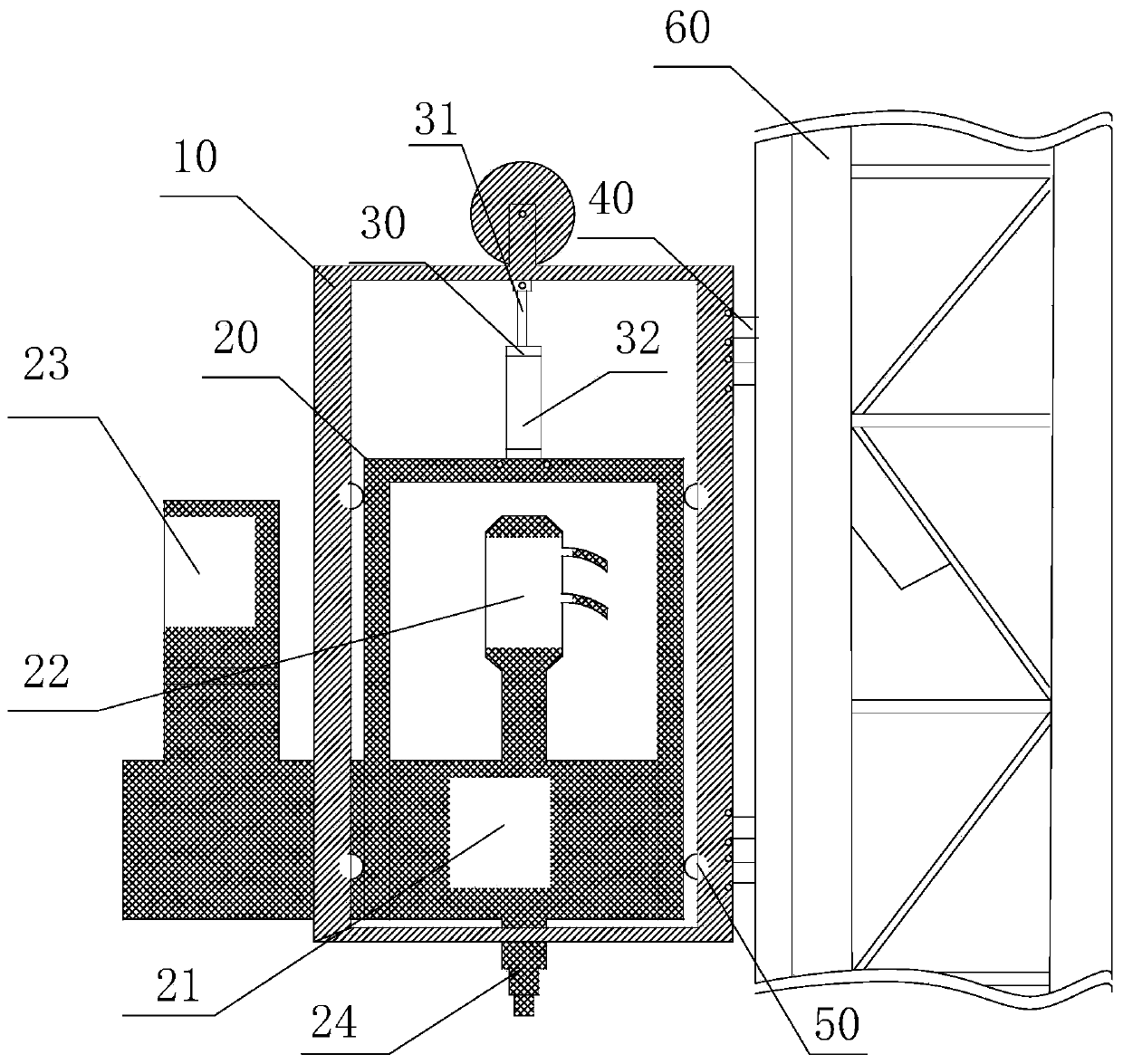
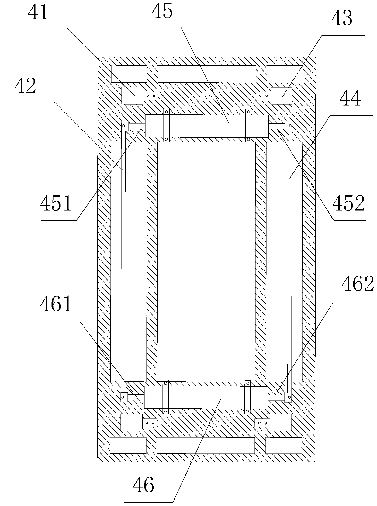
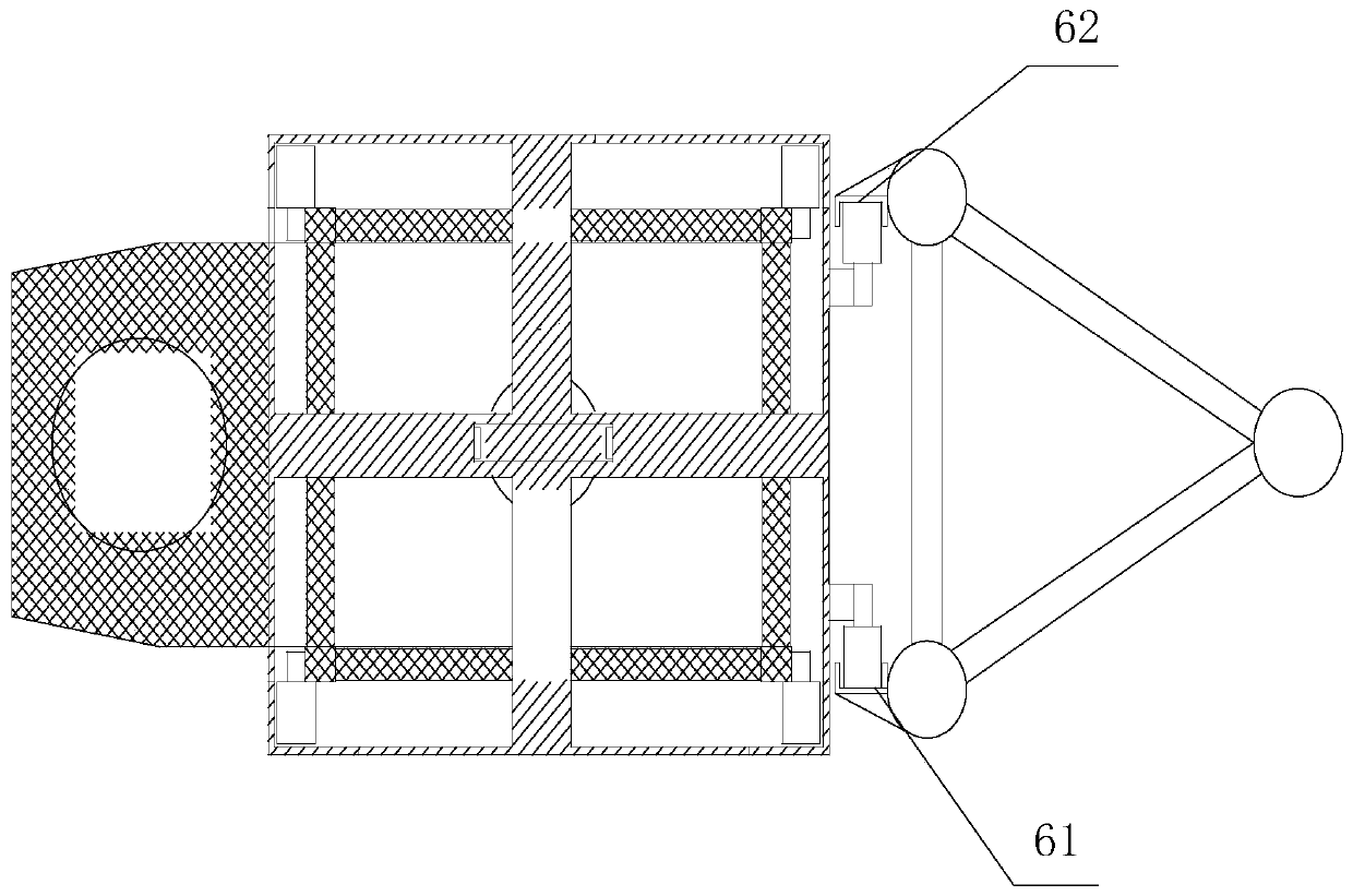
The invention provides a power head device and system and a control method. The power head device comprises a lifting basket outer frame, a push-pull assembly, a power head assembly and connecting assemblies. One end of the push-pull assembly is connected with the top of the lifting basket outer frame. The other end of the push-pull assembly is connected with the power head assembly. The power head assembly comprises a power head body arranged in the lifting basket outer frame and a power head drill bit outwards extending to the bottom of the lifting basket outer frame. The two sides of the power head body are slidingly connected with the inner wall of the lifting basket outer frame so that the power head body can rise or fall in the lifting basket outer frame. The connecting assemblies are arranged on the outer walls of the two sides of the lifting basket outer frame and used for being connected with locking structures on a truss. The power head device provides sufficient and stable feeding force, conveniently and rapidly performs drilling and is high in construction efficiency.

Description

technical field [0001] The invention relates to the technical field of building construction, in particular to a power head device, a power head system and a control method. Background technique [0002] High-pressure rotary jet grouting is to rotate and lift the spray rod with nozzles at the bottom after reaching the deep underground, and pump high-energy fluid and cement slurry at the same time to form isolated or regularly arranged cylindrical columns underground. Process of cement-soil consolidation. In order to reduce costs and improve efficiency, in recent years, self-forming holes are often used in the link of how to send spray booms underground. [0003] At present, there are three methods of self-forming holes for high-spray grouting: gravity pressure, oil cylinder chain pressure and full chain pressure. [0004] Among them, the gravity pressure method is to use the self-weight pressure of the power head to drill downward. When encountering a hard stratum, the spr...

Claims


Application Information

Patent Timeline
IPC IPC(8): E21B3/02E21B19/086E21B15/00E02D5/46
CPCE02D5/46E21B3/02E21B15/003E21B19/086
Inventor 杨玢杨松平
Owner 广东吉特高喷基础工程有限公司
Learn More