Gas rudder testing device

A test device, gas rudder technology, applied in the direction of measuring device, mechanical parts test, machine/structural parts test, etc., can solve the problem of inability to achieve precise control of gas rudder movement and automatic testing, and achieve precise action control and satisfy The effect of the data response

Active Publication Date: 2020-04-10
武汉天拓宇航智能装备有限公司
View PDF7 Cites 2 Cited by
  • Summary
  • Abstract
  • Description
  • Claims
  • Application Information

AI Technical Summary

Problems solved by technology

[0003] It plays an indispensable role in active and under-research missiles, so it is extremely important to simulate and test the relevant performance of gas rudders in the laboratory. At present, there is still a lack of comprehensive performance testing of gas rudders in the existing technology. The test device cannot achieve precise control and automatic testing of the gas rudder movement

Method used


Image

  • Gas rudder testing device
  • Gas rudder testing device
  • Gas rudder testing device

Examples


Embodiment Construction

[0026] It should be noted that, in the case of no conflict, the embodiments of the present invention and the features in the embodiments can be combined with each other. The present invention will be described in detail below with reference to the accompanying drawings and examples.

[0027] In order to enable those skilled in the art to better understand the solutions of the present invention, the following will clearly and completely describe the technical solutions in the embodiments of the present invention in conjunction with the drawings in the embodiments of the present invention. Obviously, the described embodiments are only It is an embodiment of a part of the present invention, but not all embodiments. Based on the embodiments of the present invention, all other embodiments obtained by persons of ordinary skill in the art without making creative efforts shall fall within the protection scope of the present invention.

[0028] It should be noted that the terms "first...


PUM


Abstract

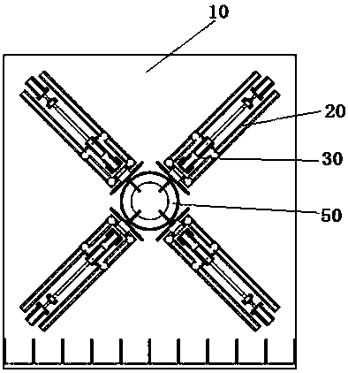
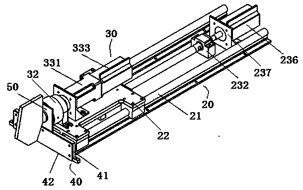
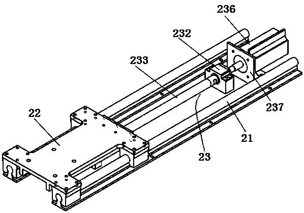
The invention provides a gas rudder testing device. The gas rudder testing device comprises a base and deflection / withdrawal control assemblies installed on the base along the same circumference. Eachdeflection / withdrawal control assembly comprises a withdrawal control assembly, including a slide rail, a sliding block and a first driving device, wherein the slide rail is installed on the base; the sliding block can be slidably installed on the slide rail. The first driving device is in driving connection with the corresponding sliding block. The device also comprises a deflection control assembly, which comprises a supporting base, a switching device and a second driving device. The supporting base is installed on the sliding block; the switching device is installed on the supporting base; and the second driving device is in driving connection with the switching device. According to the invention, multiple or one deflection / withdrawal control assembly can be used for testing a gas rudder according to actual test requirements, and each deflection / withdrawal control assembly can select synchronization or respective control according to requirements, so that the deflection performance or the withdrawal performance or the deflection performance and the withdrawal performance of the gas rudder can be cooperatively tested.

Description

technical field [0001] The invention relates to the technical field of testing equipment for the bottom surface of related rocket parts, in particular to a gas rudder testing device. Background technique [0002] The gas rudder works in the gas flow of the rocket tail jet. After the rocket engine tail jet is ignited, it changes the direction of the gas flow by deflection to provide the rocket with a turning moment. As a special wing in rocket jet, gas rudder is an important representative of thrust vector control technology. [0003] It plays an indispensable role in active and under-research missiles, so it is extremely important to simulate and test the relevant performance of gas rudders in the laboratory. At present, there is still a lack of comprehensive performance testing of gas rudders in the existing technology. The test device cannot achieve precise control and automatic testing of the gas rudder movement. Contents of the invention [0004] The main purpose of ...

Claims


Application Information

Patent Timeline
Patent Type & Authority Applications(China)
IPC IPC(8): G01M13/00
CPCG01M13/00
Inventor 许冶王维王重阳夏俊辉万建武李雷涂克恒
Owner 武汉天拓宇航智能装备有限公司
Why Eureka
Try Eureka