Stamping die with auxiliary feeding mechanism

A stamping die and feeding technology is applied in the field of stamping die with auxiliary feeding mechanism to achieve the effect of reducing personal accidents and convenient use.

Inactive Publication Date: 2020-04-14
徐珊珊
View PDF6 Cites 0 Cited by
  • Summary
  • Abstract
  • Description
  • Claims
  • Application Information

AI Technical Summary

Problems solved by technology

The existing semi-automatic stamping machines are generally loaded m

Method used


Image

  • Stamping die with auxiliary feeding mechanism
  • Stamping die with auxiliary feeding mechanism
  • Stamping die with auxiliary feeding mechanism

Examples


Example Embodiment

[0035] The following will clearly and completely describe the technical solutions in the embodiments of the present invention with reference to the accompanying drawings in the embodiments of the present invention. Obviously, the described embodiments are only some, not all, embodiments of the present invention. Based on the embodiments of the present invention, all other embodiments obtained by persons of ordinary skill in the art without making creative efforts belong to the protection scope of the present invention.

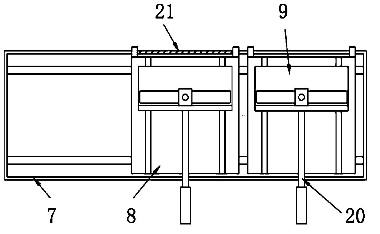
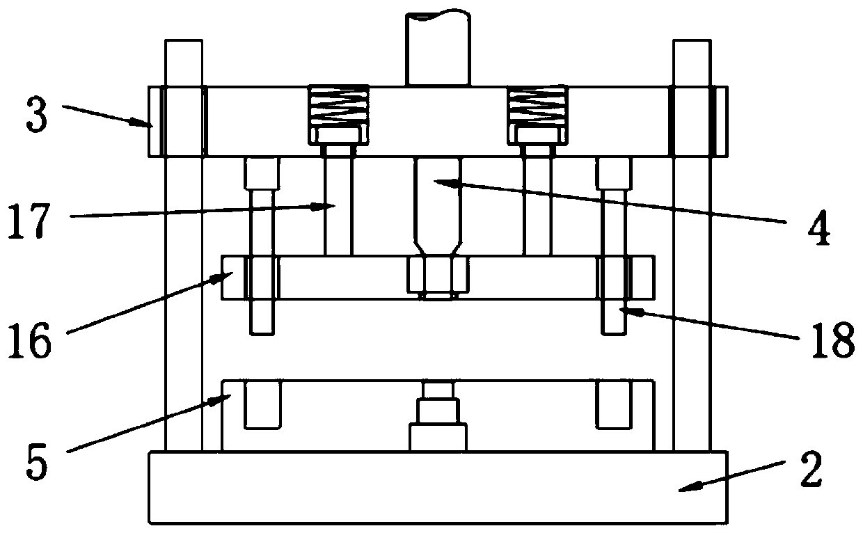
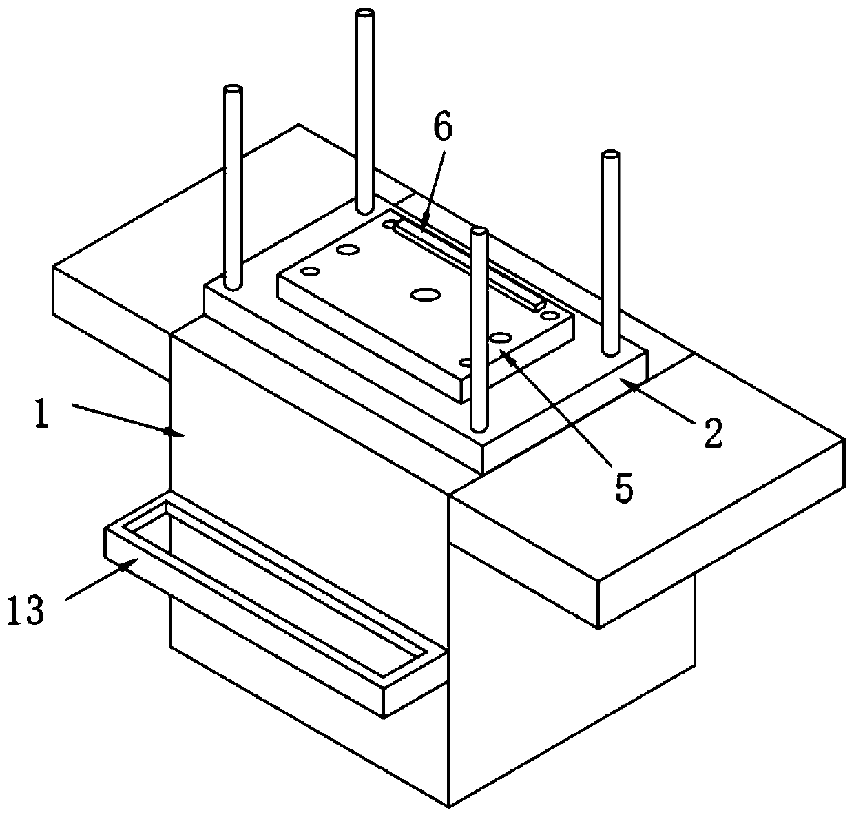
[0036] see Figure 1-5 , the present invention provides a stamping die with an auxiliary feeding mechanism, comprising a frame 1, the lower end of the frame 1 is provided with a lower die fixing device 2, and the upper end of the frame 1 is provided with an upper die fixing device 3 , the upper mold fixing device 3 is slidingly connected with the frame 1 through a slide bar, and the lower side of the upper mold fixing device 3 is provided with a stamping modul...


PUM


Abstract

The invention discloses a stamping die with an auxiliary feeding mechanism, which comprises a rack, wherein the lower end of the rack is provided with a lower die fixing device; the upper end of the rack is provided with an upper die fixing device; the upper die fixing device is connected with the rack in a sliding mode through a sliding rod; a stamping module is arranged on the lower side of theupper die fixing device; a lower die plate is arranged on the upper side of the lower die fixing device; a limiting module is arranged on one side of the upper end of the lower die plate; an auxiliarymechanism is arranged on the outer side of the rack and comprises a fixing frame; a limiting groove is formed in the inner side of the fixing frame; a sliding rail is arranged in the limiting groove;two connecting seats are arranged on the sliding rail; a material carrying plate is arranged on each connecting seat; a guide groove is formed in the bottom of each connecting seat; and the materialcarrying plate is connected with the connecting seat in a sliding mode through a sliding groove. Compared with a traditional stamping die, the stamping die has the advantages that feeding is conductedthrough the auxiliary mechanism, and the occurrence of personal accidents is greatly reduced.

Description

technical field [0001] The invention relates to the technical field of stamping dies, in particular to a stamping die with an auxiliary feeding mechanism. Background technique [0002] The stamping mold base generally includes an upper mold base, a guide unloading plate and a lower mold base. The stamping mold base is also equipped with a guiding mechanism. At present, when the factory uses the stamping mold base, it generally adopts the traditional manual loading and unloading. found in the production process. Stamping is a forming processing method that applies external force to plates, strips, pipes and profiles by presses and molds to cause plastic deformation or separation to obtain workpieces (stamping parts) of required shape and size. According to different processing methods, punching machines can be divided into two types: automatic punching machines and semi-automatic punching machines. Existing semi-automatic stamping machines are generally loaded manually, onc...

Claims


Application Information

Patent Timeline
IPC IPC(8): B21D43/02
CPCB21D43/02
Inventor 徐珊珊
Owner 徐珊珊
Why Eureka
Try Eureka