Chamfering equipment

A chamfering and equipment technology, applied in metal processing equipment, measuring/indicating equipment, metal processing machinery parts, etc., can solve the problems of low work efficiency and inability to ensure 100% accuracy of workpieces, and achieve the effect of improving work efficiency

Active Publication Date: 2020-04-14
江苏南钢通恒特材科技有限公司
View PDF5 Cites 1 Cited by
  • Summary
  • Abstract
  • Description
  • Claims
  • Application Information

AI Technical Summary

Problems solved by technology

[0004] The purpose of the present invention is to provide a chamfering device to solve the technical problem of manual detection accuracy and chamfering of rod-shaped metal parts to a certain extent, which cannot guarantee 100% accuracy of the workpiece and the technical problems of low work efficiency

Method used


Image

  • Chamfering equipment
  • Chamfering equipment
  • Chamfering equipment

Examples


Embodiment

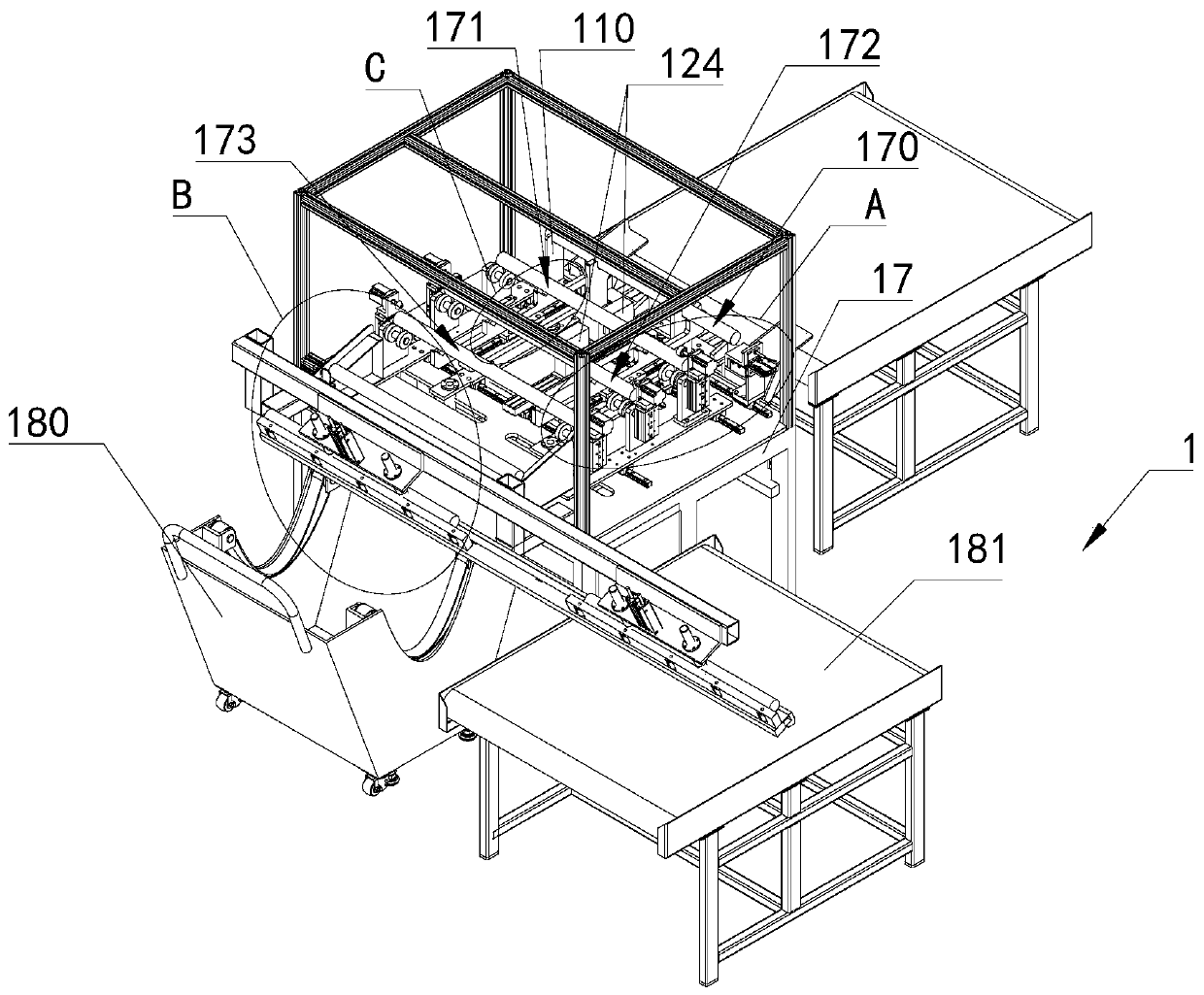
[0051] The chamfering equipment provided in this embodiment is used for automatic precision detection and automatic chamfering treatment of rod-shaped metal parts. Wherein, optionally, the rod-shaped metal piece is a rod-shaped metal piece processed by a silver-brightening process, specifically, the rod-shaped metal piece is a steel rod processed by a silver-brightening process.

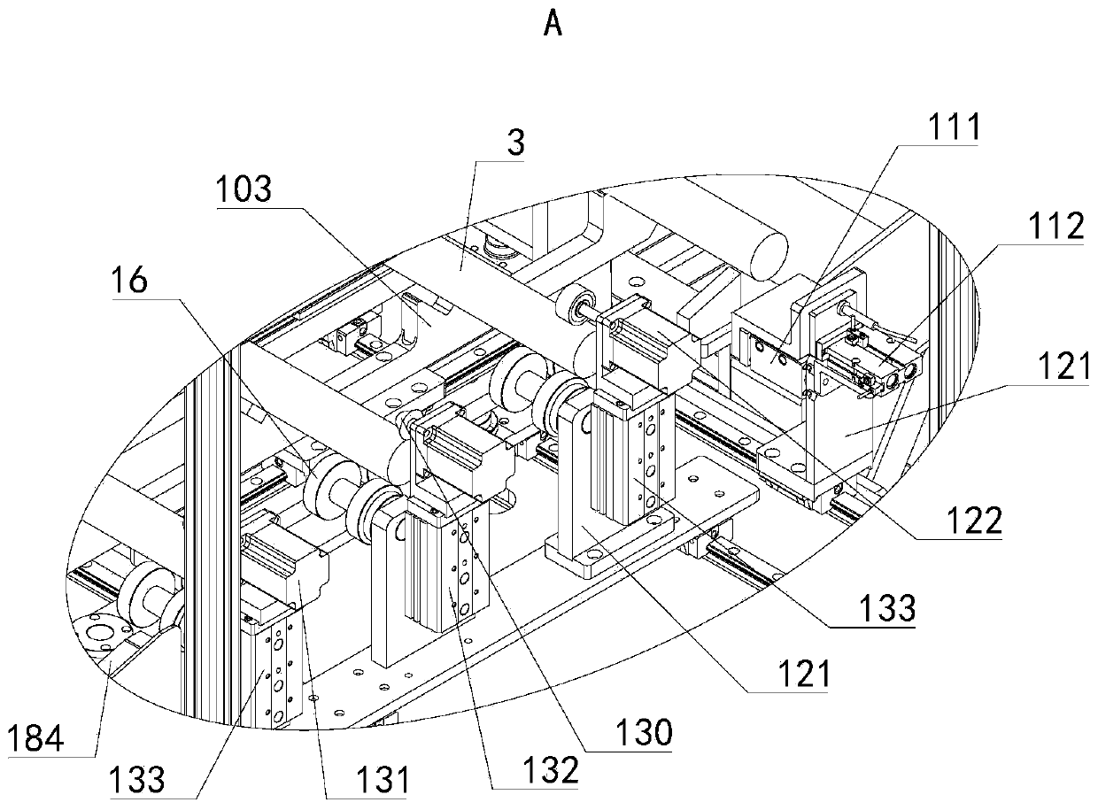
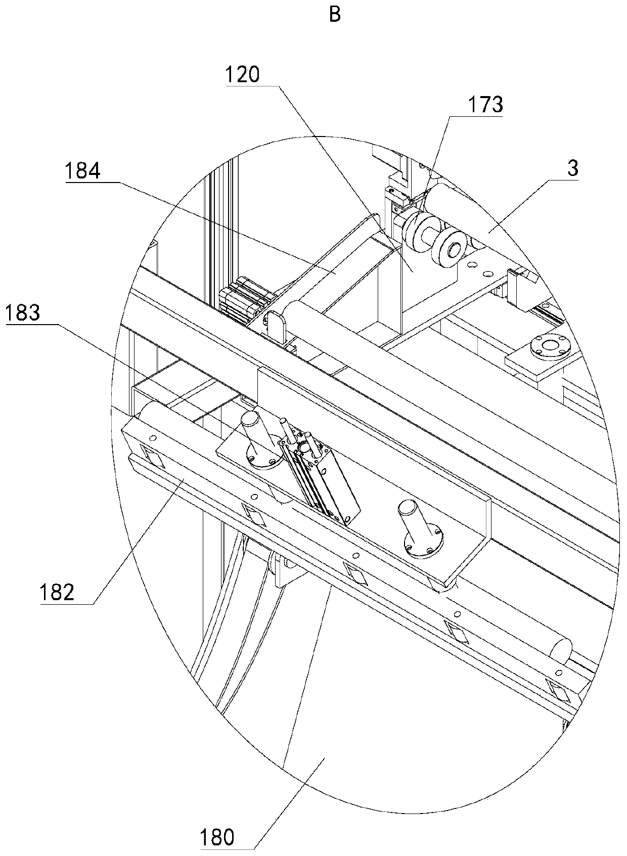
[0052] see Figure 1 to Figure 5 As shown, the chamfering equipment 1 provided in this embodiment includes a transmission mechanism, a controller 15 and a precision detection mechanism and a chamfering mechanism arranged in sequence.

[0053] The transmission mechanism can move the rod-shaped metal piece 3 from the precision detection mechanism to the chamfering mechanism, so that the two ends of the rod-shaped metal piece 3 can be chamfered through the chamfering mechanism, and the direction from the precision detection mechanism to the chamfering mechanism is the transmission The transport directi...


PUM


Abstract

The invention relates to the technical field of chamfering machinery, in particular to chamfering equipment. The chamfering equipment comprises a conveying mechanism, a controller, a precision detection mechanism and a chamfering mechanism, wherein the precision detection mechanism and the chamfering mechanism are arranged in sequence; the conveying mechanism can move a rod-shaped metal piece fromthe precision detection mechanism to the chamfering mechanism, so that the two ends of the rod-shaped metal piece are chamfered through the chamfering mechanism; the precision detection mechanism iselectrically connected with the controller; the precision detection mechanism can detect the size of the rod-shaped metal piece, and the controller can judge whether the size precision of the rod-shaped metal piece reaches the standard or not. The chamfering equipment comprises a controller, a precision detection mechanism, a chamfering mechanism and a conveying mechanism. The functions of automatic precision detection, automatic chamfering, automatic judgment of whether the size precision is qualified or not and automatic conveying among the machining stations are integrated, and compared with an existing manual precision detection and chamfering method, the precision percent of pass of the rod-shaped metal pieces entering a finish machining procedure can be increased, and the working efficiency can be improved.

Description

technical field [0001] The invention relates to the technical field of chamfering machinery, in particular to chamfering equipment. Background technique [0002] Rod metal parts are important materials for components such as automobile half shafts, gears, steering racks and drive shafts. Before the bar-shaped metal parts become the above-mentioned parts, they need to be finished by CNC machine tools. Due to the high precision of the CNC machine tools, it is necessary to solve the problems of diameter deviation, length deviation and unchamfering of the bar-shaped metal parts in the rough machining stage. In order to avoid the impact on the life of the finishing tool due to unqualified workpiece accuracy, and even cause unnecessary losses to the CNC machine tool. [0003] In related technologies, the diameter and length of the bar-shaped metal parts are usually manually detected, and the chamfering is performed manually. This method of manually detecting the accuracy and cham...

Claims


Application Information

Patent Timeline
IPC IPC(8): B23D79/00B23Q17/00
CPCB23D79/00B23Q17/00
Inventor 张青鲍新城余虎蒋振
Owner 江苏南钢通恒特材科技有限公司
Why Eureka
Try Eureka