New energy vehicle charging pile

A technology for new energy vehicles and charging piles, applied in electric vehicle charging technology, charging stations, electric vehicles, etc., can solve the problems of electric vehicles being unable to be charged, occupying the parking space in front of the charging pile in the community, etc., and achieve standardized charging operation and connection. neat line effect

Active Publication Date: 2020-04-14
UNIV FOR SCI & TECH ZHENGZHOU
View PDF7 Cites 6 Cited by
  • Summary
  • Abstract
  • Description
  • Claims
  • Application Information

AI Technical Summary

Problems solved by technology

[0004] The main purpose of the invention is to solve the problem that fuel vehicles occupy the parking space in front of the charging pile in the community, making it impossible for electric vehicles to charge

Method used


Image

  • New energy vehicle charging pile
  • New energy vehicle charging pile
  • New energy vehicle charging pile

Examples


Embodiment 2

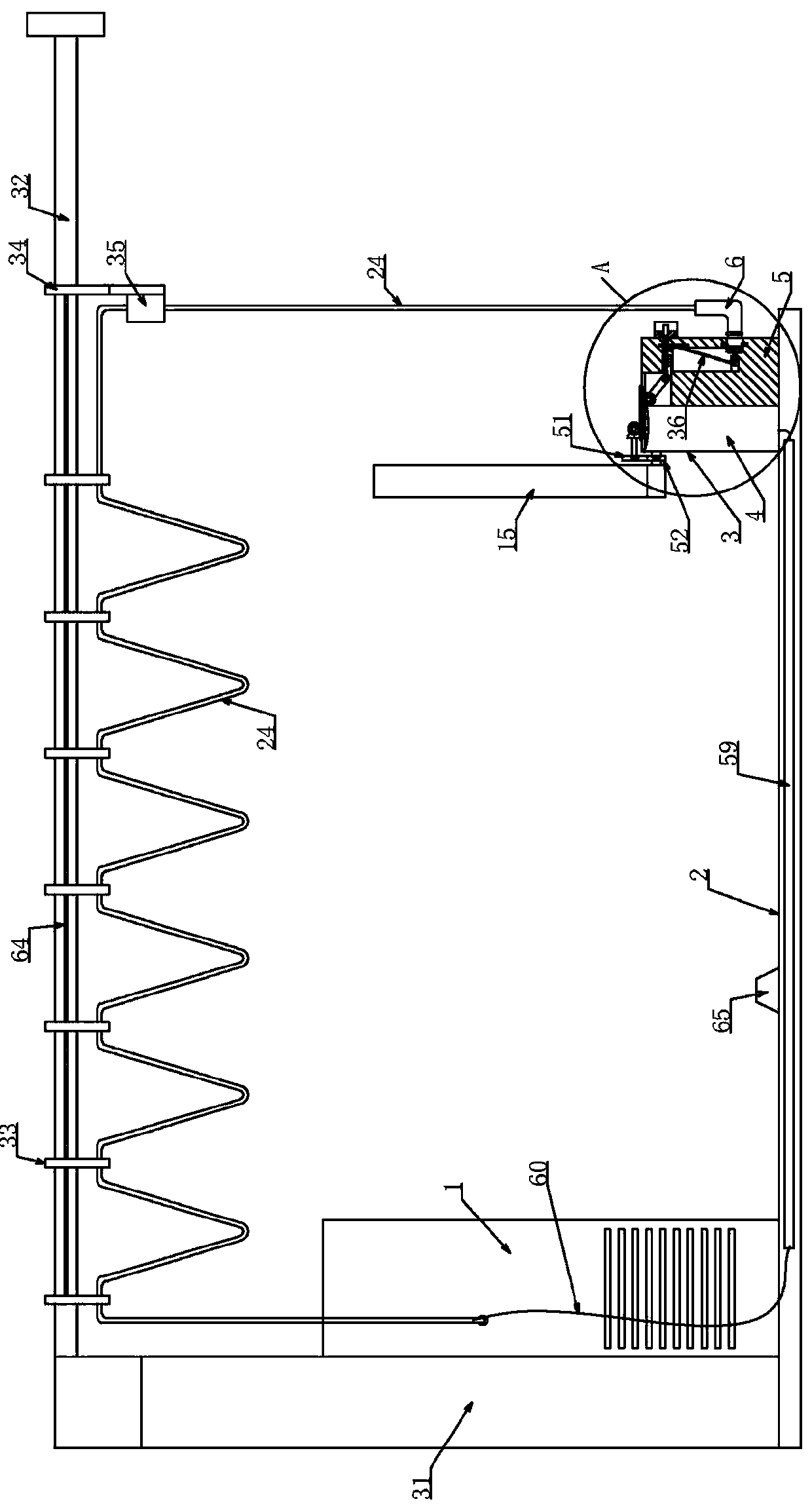
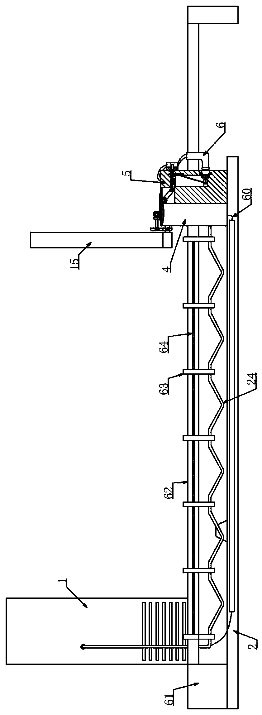
[0024] Embodiment 2, on the basis of Embodiment 1, further includes a wire management device for accommodating the connection wire 24 between the main body of the charging pile 1 and the charging gun 6 . The wire management device is used to prevent the connection wire 24 between the charging gun 6 and the body of the charging pile 1 from being entangled when the electric vehicle drives into the parking space 2 .

Embodiment 3

[0025] Embodiment 3. On the basis of Embodiment 2, the cable management device includes a column 31 fixed on the left side of the body of the charging pile 1. The upper end of the column 31 protrudes upward from the body of the charging pile 1 and is fixed with a support extending to the right. The rod 32 is horizontally slidably connected with a plurality of slip rings 33 , and the connection wire 24 of the charging gun 6 is fixed at multiple points through the plurality of slip rings 33 . Preferably, a sliding rod 34 is slidably connected to the support rod 32 on the right side of the rightmost slip ring 33, and a vertical fixing cylinder 35 is installed on the left side of the sliding rod 34, and the connecting wire 24 of the charging gun 6 passes through The rightmost slip ring 33 is connected to the charging gun 6 after passing through the fixing cylinder 35 . Of course, the sliding rod 34 can also be replaced by a slip ring 33 . Preferably, the connecting wire 24 of the...

Embodiment 5

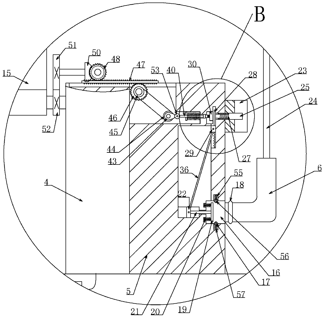
[0027] Embodiment 5, on the basis of Embodiment 1, the second transmission mechanism includes a first elastic telescopic rod 38 fixed on the back of the second sensor 30, and the first elastic telescopic rod 38 makes when the second trigger rod 25 touches When reaching the second sensor 30, the second sensor 30 has a certain amount of retraction margin, and the structure is relatively flexible. When the second sensor 30 is fixed on the sensor substrate, the first elastic telescopic rod 38 is mounted on the back of the sensor substrate. The first elastic telescopic rod 38 comprises a sleeve, and a movable rod is slidably connected in the sleeve (the sliding position of the movable rod in the sleeve is limited, for example, it has the rightmost or leftmost position relative to the sleeve, and now it can A sliding groove is set in the sleeve, and a sliding block (slidably fitted in the sliding groove) is fixed on the movable rod, and the eighth spring 39 is set on the movable rod...


PUM


Abstract

The invention mainly aims to provide a new energy vehicle charging pile to solve the problem that an electric vehicle cannot be charged due to the fact that an existing fuel vehicle occupies a parkingspace in front of a community charging pile. According to the invention, the insertion groove is matched with the charging gun, the charging gun connecting wire is matched with the arc-shaped wire clamp, the second sensor is lifted and moved by the lifting rod, and the first sensor in the charging hole of the charging gun is matched with the charger in the charging port of the electric vehicle; the problem that the gasoline vehicle occupies the parking space in front of the electric vehicle charging pile is effectively solved, and a great guarantee is provided for charging of the electric vehicle. And by means of the mechanism, after a user uses the charging gun, the charging gun is inserted into the insertion groove, the charging gun connecting wire is clamped into the arc-shaped wire clamp, otherwise, the lifting rod is not lifted, and the charging operation of a driver is standardized. And the charging gun connecting wire is clamped into the arc-shaped wire clamp, so that the connecting wire is tidier.

Description

technical field [0001] The invention belongs to the field of new energy, and in particular relates to a charging pile for a new energy vehicle. Background technique [0002] With the advantages of energy saving, emission reduction, environmental protection and no pollution, new energy vehicles gradually replace traditional vehicles and are widely used. In the process of using new energy vehicles, their charging piles are used as supporting devices, and they are constantly being built in parking lots, service areas and other places. [0003] However, when charging piles for centralized charging are built in the community, they are often built in a centralized manner. A row of charging piles is built, and there is a parking space in front of each charging pile. Covered with canopy. However, due to the continuous improvement of people's living standards this year, the number of cars is also increasing, especially in communities with insufficient parking spaces, where fuel veh...

Claims


Application Information

Patent Timeline
IPC IPC(8): B60L53/31B60L53/16
CPCB60L53/16B60L53/31Y02T10/70Y02T10/7072Y02T90/12Y02T90/14
Inventor 陈林林宋鹏飞陈贝贝李伟杨晨
Owner UNIV FOR SCI & TECH ZHENGZHOU
Why Eureka
Try Eureka