Check patentability & draft patents in minutes with Patsnap Eureka AI!

Polaroid hole detection equipment

A technology for testing equipment and polarizers, which is applied in the direction of optical testing for flaws/defects, measuring devices, and material analysis through optical means. It can solve problems such as low efficiency, difficulty in achieving full product inspection, and unqualified products.

Active Publication Date: 2020-04-17
BEIJING FOCUSIGHT TECH
View PDF7 Cites 5 Cited by
  • Summary
  • Abstract
  • Description
  • Claims
  • Application Information

AI Technical Summary

Problems solved by technology

[0003] At present, the method of detecting this defect in the industry is generally manual sampling, which is inefficient and will produce unqualified products, making it difficult to achieve the purpose of overall product inspection

Method used


Image

  • Polaroid hole detection equipment
  • Polaroid hole detection equipment
  • Polaroid hole detection equipment

Examples


Embodiment Construction

[0050] The present invention will now be further described in conjunction with the accompanying drawings and preferred embodiments. These drawings are all simplified schematic diagrams, which only illustrate the basic structure of the present invention in a schematic manner, so they only show the configurations related to the present invention.

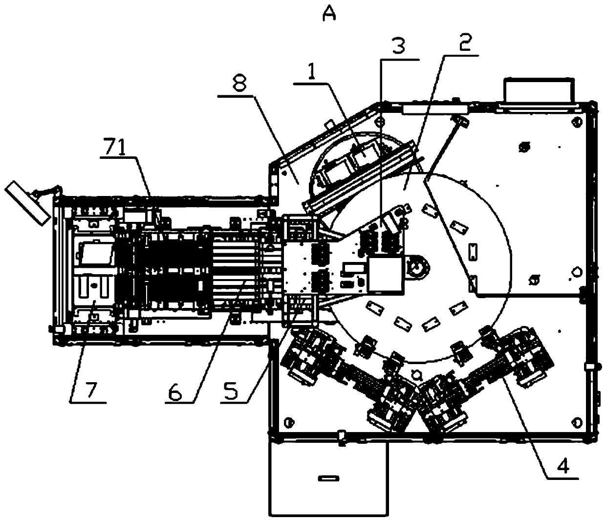
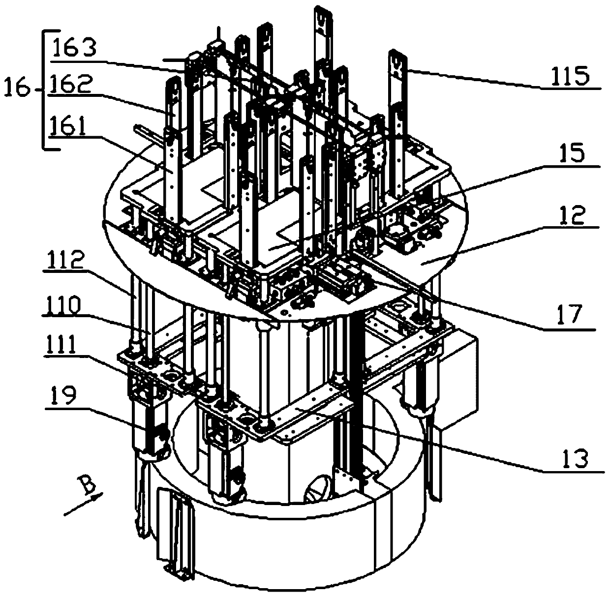
[0051] Such as figure 1 with 2 As shown, a polarizer hole detection device includes a frame 8, and the frame 8 is sequentially provided with a feeding mechanism 1, a rotating mechanism 2, a pre-pressing mechanism 3, a detection mechanism 4, a blanking mechanism 5, and a waste kicking mechanism 6 And receiving mechanism 7, also be provided with on the frame 8 and drive parts in feeding mechanism 1, rotating mechanism 2, pre-pressing mechanism 3, detection mechanism 4, unloading mechanism 5, kick waste mechanism 6, receiving mechanism 7 Electrically connected PLC controller (not shown in the figure), each action is controlled by the P...


PUM


Abstract

The invention relates to the technical field of hole defect detection equipment, in particular to polaroid hole detection equipment. The polaroid hole detection equipment comprises a rack, and a feeding mechanism, a rotating mechanism, a pre-pressing mechanism, a detection mechanism, a discharging mechanism, a waste rejecting mechanism and a material receiving mechanism are sequentially arranged on the rack. A PLC electrically connected with driving components in the feeding mechanism, the rotating mechanism, the pre-pressing mechanism, the detection mechanism, the discharging mechanism, the waste rejecting mechanism and the material receiving mechanism is further arranged on the rack, and each action is controlled by the PLC. Linkage is achieved by controlling each mechanism, and actionsof rapid grabbing and rotating, rapid detection, rapid conveying and rapid material receiving of polaroids are achieved.

Description

technical field [0001] The invention relates to the technical field of hole defect detection equipment, in particular to a polarizer hole detection equipment. Background technique [0002] The polarizer product is a linearly polarized component. It is an optical product that uses the light spots in each light spot group to be independently responsible for the performance. It needs to punch holes in the product. After the holes are punched, defects will occur on the edge of the holes, resulting in unqualified products. , in order to avoid this situation, it is necessary to fully detect this part. [0003] At present, the method of detecting this defect in the industry is generally manual sampling, which is inefficient and will produce unqualified products, and it is difficult to achieve the purpose of full inspection of the product as a whole. Contents of the invention [0004] The technical problem to be solved by the present invention is to overcome the deficiencies in t...

Claims


Application Information

Patent Timeline
IPC IPC(8): B07C5/00B07C5/02B07C5/36B07C5/38G01N21/95
CPCB07C5/00B07C5/02B07C5/362B07C5/38G01N21/95G01N2021/9511
Inventor 王郑王岩松和江镇方志斌秦学文张飞
Owner BEIJING FOCUSIGHT TECH
Features
  • R&D
  • Intellectual Property
  • Life Sciences
  • Materials
  • Tech Scout
  • Unparalleled Data Quality
  • Higher Quality Content
  • 60% Fewer Hallucinations
Learn More