
Middle frame proofing method

A technology of middle frame and plate, which is applied in the direction of coating, etc., can solve the problems of increasing the development cost of injection molds and prolonging the research and development cycle.

Active Publication Date: 2021-11-16
DONGGUAN CHANGYING PRECISION TECH CO LTD
View PDF5 Cites 0 Cited by
  • Summary
  • Abstract
  • Description
  • Claims
  • Application Information

AI Technical Summary

Problems solved by technology

Injection molding needs to make injection molds. The traditional middle frame proofing method needs to make an injection mold according to each sample, which will not only prolong the research and development cycle, but also lead to a significant increase in the development cost of injection molds.

Method used


Image

  • Middle frame proofing method
  • Middle frame proofing method
  • Middle frame proofing method

Examples


Embodiment Construction

[0042] To facilitate understanding of the present invention, with reference to the following drawings related to the present invention will be more fully described. The figures given in the preferred embodiment of the present invention. However, the present invention can be implemented in many different forms, is not limited to the embodiments described herein. Conversely, the purpose of providing these examples is to make the understanding of the disclosure of the present invention more thoroughly.

[0043] It should be noted that when the element is referred to as "fixed to" another element, it can be directly in another element or may exist in the hidden element. When an element is considered to be "connected" another element, it can be directly connected to another element or may exist at the same time.

[0044] All technical and scientific terms used herein are commonly understood by those skilled in the art of the present invention, unless otherwise defined. The terminology us...


PUM


Abstract

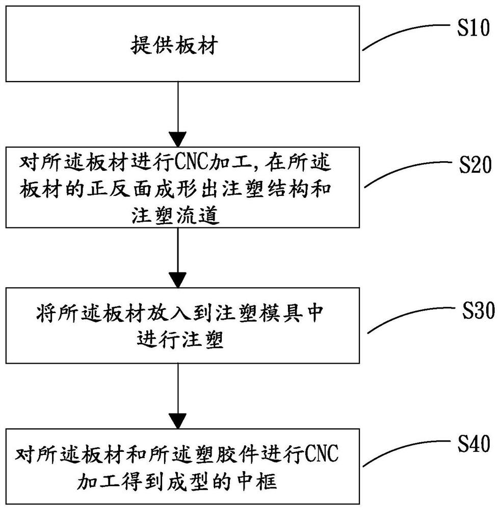
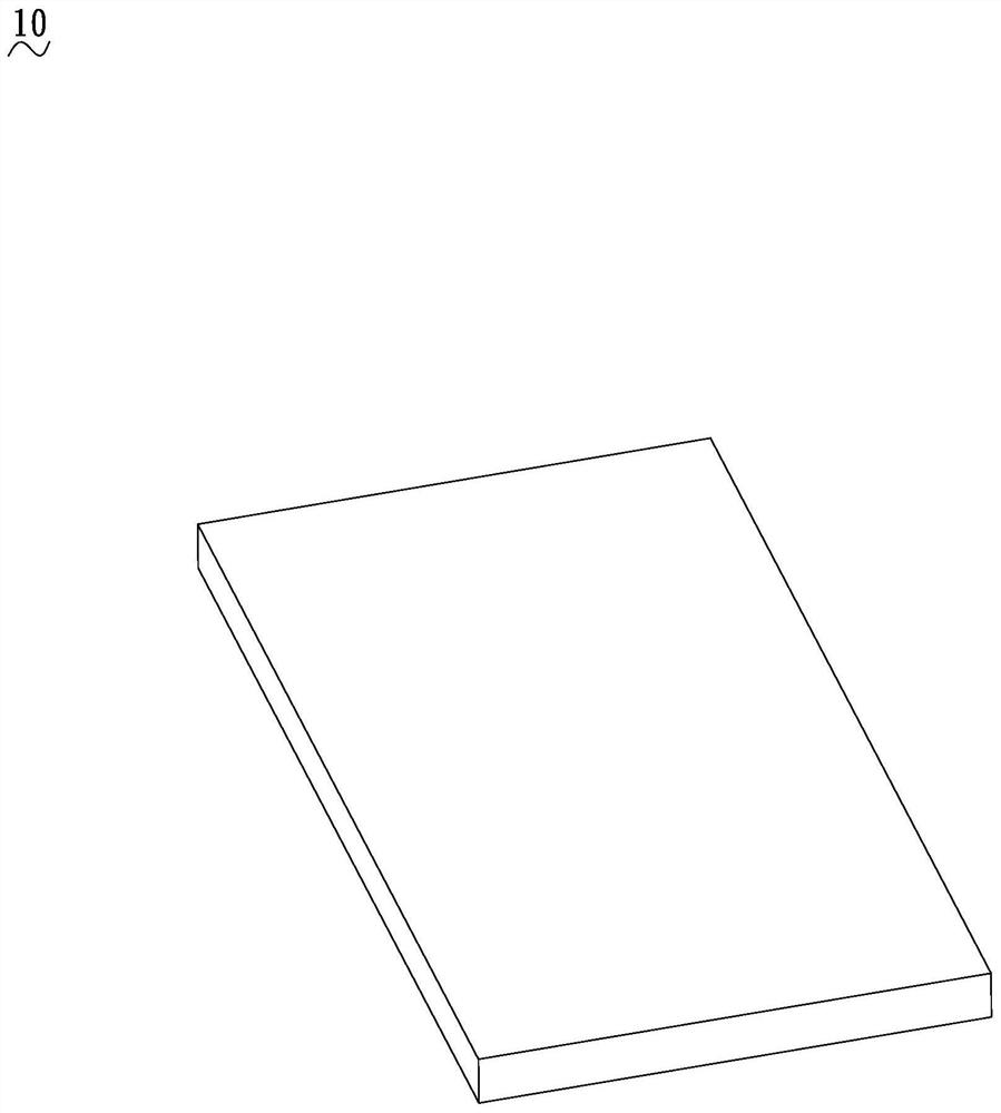
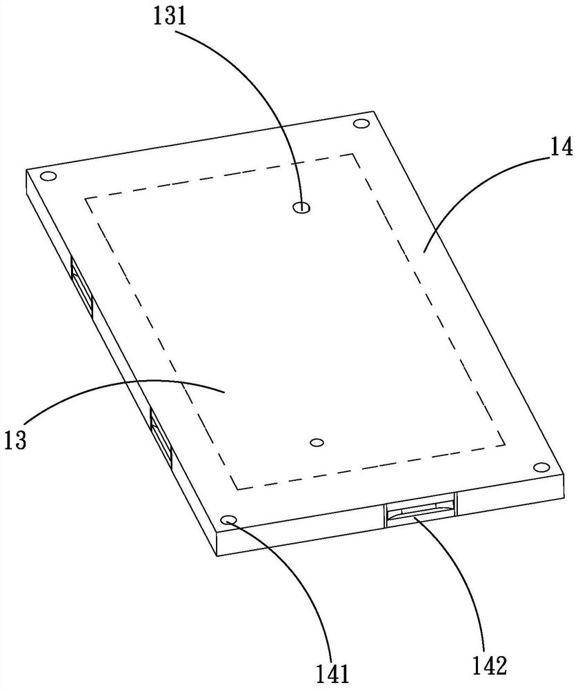
The invention relates to a middle frame proofing method, comprising the steps of: providing a plate; performing CNC processing on the plate, forming an injection structure and an injection flow channel on the front and back of the plate; the injection flow channel is connected with the injection structure; the front and back of the plate are injected The area outside the flow channel and the injection molding structure is the sealing surface; put the plate into the injection mold for injection molding, the injection mold is close to the sealing surface, and the plastic material is drained to the injection molding structure through the injection flow channel. Attached plastic parts are formed at the injection molding structure; CNC processing is performed on the plate and plastic parts to obtain the formed middle frame. With the above middle frame proofing method, after the plate is selected, the injection mold does not need to be adjusted according to the style of the middle frame, so as to realize the universal use of the injection mold and rapid proofing, which can not only shorten the research and development cycle, but also reduce the cost of the injection mold. Development costs.

Description

Technical field [0001] The present invention relates to the field of electronics manufacturing technology, particularly to a block sampling method. Background technique [0002] With the development of touch screen technology, most of today's electronic products are based on the touch screen as the display screen and input tool. Thus, the structural design of electronic products also gradually changed to a touch screen, block, and a combination of the bottom cover. Wherein the block as the main carrier of electronic components, such as a control board, a control chip, an antenna, a battery, a data input terminal, etc., and other electronic parts mounted on the intermediate frame. [0003] In the product development stage, the need for proofing product designs, the sample was subjected to proofing test, after the test passes before entering the mass production stage. Therefore, before determining the final design of the product, the product might require multiple proofing. Block f...

Claims


Application Information

Patent Timeline
Patent Type & Authority Patents(China)
IPC IPC(8): B29C45/14B29C45/17B29C45/26
CPCB29C45/14221B29C45/17B29C45/26
Inventor 张科黄浩陈国声匡秋吉伍新城
Owner DONGGUAN CHANGYING PRECISION TECH CO LTD
Learn More