Synchronous register impressing system and impressing method

An embossing machine and control system technology, which is applied in the field of synchronous embossing embossing system, can solve the problems of insufficient indentation depth, easy blurring, deviation of finished pattern and pattern, etc., and achieve the effect of long embossing time and high simulation degree

Active Publication Date: 2020-04-17
WELLMADE FLOOR IND CO LTD
View PDF18 Cites 9 Cited by
  • Summary
  • Abstract
  • Description
  • Claims
  • Application Information

AI Technical Summary

Problems solved by technology

The disadvantages of this are: 1. The contact time between the pattern roller and the floor is extremely short, resulting in insufficient indentation depth, easy deformation, and easy blurring
Second, the pattern and the pattern deviate
Although the speed difference between the printing layer and the substrate layer can be adjusted by raising the temperature in this application, the printing layer is a very thin plastic film. During the pressing process, the printing layer 12 passes through the first press roller 25 and the feed roller 31 to convey, during this process, the printing layer will be stretched and narrowed, resulting in deformation in both length and width. Even if the registration transfer system can adjust the deviation in length, the deviation in width cannot be avoided , so the final product will deviate from the pattern and the pattern, especially on both sides of the plate, the deviation is serious

Method used


Image

  • Synchronous register impressing system and impressing method
  • Synchronous register impressing system and impressing method
  • Synchronous register impressing system and impressing method

Examples


Embodiment 1

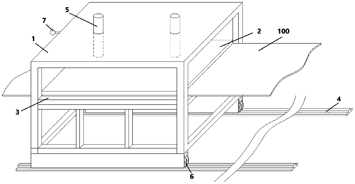
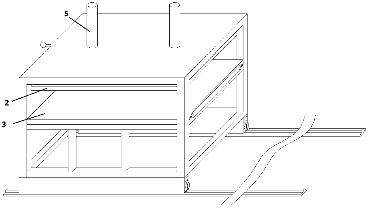
[0036] Such as Figure 1-4 As shown, the synchronous embossing system includes a embossing machine and a plate 100 to be embossed, and is characterized in that: the imprinting machine includes a frame 1, an upper platen 2, a lower platen 3, and a guide rail 4. The upper pressing plate is connected to the top of the frame through the pressing down driving device 5, the lower pressing plate is arranged in the middle of the frame, the bottom of the frame is provided with a roller 6 matching the guide rail, and the length of the guide rail is greater than or equal to the length of the frame*2 , also includes a frame driving device (not shown in the figure), which is used to drive the frame to move on the guide rail. Pattern, the width of the upper platen is equal to or slightly wider than the plate, and the size of the lower platen and the upper platen is equal or slightly larger than the upper platen.

[0037]The embossing machine also includes an image recognition system 7 and ...

Embodiment 2

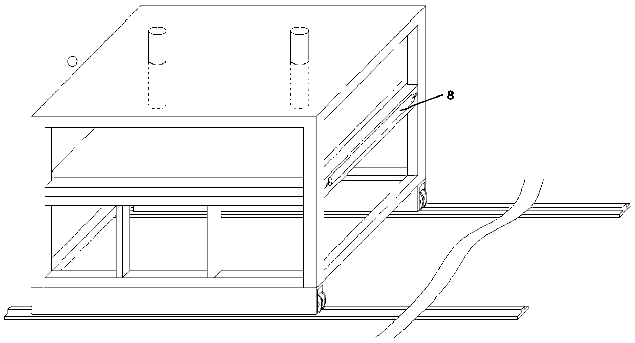
[0041] The structure of this embodiment is basically the same as that of Embodiment 1. The difference is that it also includes a deviation correction device arranged on the lower platen. The deviation correction device is two hydraulic push rods 9 arranged symmetrically. On both sides of the feeding direction of the embossing machine, the image recognition system is located in the middle of the frame above the feeding side of the embossing machine, and the plate to be embossed is provided with a centerline mark on the centerline of the starting position of each unit, so The centerline position of the rack is pre-recorded in the above image recognition system, and the image recognition system sends both the centerline position of the rack and the signal of the centerline mark to the control system, and the control system compares the centerline mark with the centerline position of the rack, and if the centerline If the position of the mark is to the left relative to the center l...

Embodiment 3

[0043] The structure of this embodiment is basically the same as that of Embodiment 2, the difference is that it also includes a heating device (not shown in the figure) for uniformly heating the upper platen, and conventional heating devices can be used, such as electric heating and thermal oil heating.


PUM


Abstract

The invention discloses a synchronous register impressing system comprising an impressing machine and a to-be-impressed plate; the impressing system is characterized in that the impressing machine comprises a rack, an upper pressing plate, a lower pressing plate and a guide rail; the upper pressing plate is connected with the top of the rack through a lower pressing driving device; the lower pressing plate is arranged in the middle of the rack; rollers matched with the guide rail are arranged at the bottom of the rack; the impressing machine also comprises a rack driving device, the rack driving device is used for driving the rack to move on the guide rail, concave-convex patterns corresponding to patterns on the surface of the to-be-impressed plate are arranged on one side, facing the lower pressing plate, of the upper pressing plate, the width of the upper pressing plate is equal to or slightly larger than that of the plate, and the lower pressing plate and the upper pressing plate are equal in size or the lower pressing plate is slightly larger than the upper pressing plate in size. The invention further discloses the synchronous register impressing method. Clear and stable patterns can be formed on the surface of the plate, and the patterns and the concave-convex patterns can be accurately aligned.

Description

technical field [0001] The invention relates to a synchronous pattern-aligning embossing system and a synchronous pattern-aligning embossing method. Background technique [0002] Synchronous alignment has always been a difficult point in the production of plastic sheets. Synchronous matching technology can form concave-convex patterns that match the pattern on the surface of the board, making the pattern more three-dimensional and realistic. The current synchronous alignment technology is mainly realized by multi-roller calendering. During the production process, the transmission of the substrate and the printing film is prone to asynchronous phenomena, resulting in misalignment of the substrate and the printing film. Not only the pattern is blurred, but also the pattern and the concave-convex pattern Mismatch will seriously affect the look and feel of the board. [0003] US patent document US10384427B2 discloses a plastic floor with a printed pattern. The concave-convex p...

Claims


Application Information

Patent Timeline
Patent Type & Authority Applications(China)
IPC IPC(8): B29C59/02B29L7/00
CPCB29C59/02B29C59/002B29L2007/002
Inventor 张浩
Owner WELLMADE FLOOR IND CO LTD
Why Eureka
Try Eureka