
Bifocal bidirectional combined imaging optical system

An optical system and combined imaging technology, which is applied in the field of optical imaging, can solve the problems of reducing the accuracy and speed of automation instructions, inhibiting the development of intelligent transportation, and complex image plane combination, etc., to achieve compact structure, high miniaturization, and high imaging quality. Effect

Inactive Publication Date: 2020-04-17
TIANJIN UNIV
View PDF6 Cites 0 Cited by
  • Summary
  • Abstract
  • Description
  • Claims
  • Application Information

AI Technical Summary

Problems solved by technology

[0002] Traditional optical lenses can only be used to observe objects in a single direction
In the scene of multi-directional observation, the cooperation of multiple sets of lenses is required, but it is difficult for multiple sets of lenses to achieve complete synchronization and coordination, and the combination of image planes is also relatively complicated, which greatly reduces the accuracy and speed requirements of automation instructions
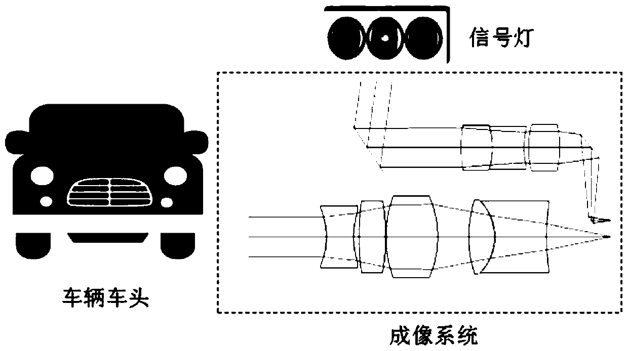
[0003] For example, in traffic monitoring, the monoscopic camera has a single field of view for information acquisition and too little information, so it cannot intelligently and automatically judge whether the vehicle has violated traffic regulations. It can monitor vehicles at a fixed distance in a fixed scene, which greatly inhibits the development of intelligent transportation

Method used


Image

  • Bifocal bidirectional combined imaging optical system
  • Bifocal bidirectional combined imaging optical system
  • Bifocal bidirectional combined imaging optical system

Examples


Embodiment Construction

[0021] The present invention will be described in further detail below in conjunction with the accompanying drawings and specific embodiments. It should be understood that the specific embodiments described here are only used to explain the present invention, not to limit the present invention.

[0022] It should be noted that the terminology used here is only for describing specific implementations, and is not intended to limit the exemplary implementations according to the present application. As used herein, unless the context clearly indicates otherwise, the singular form is also intended to include the plural form. In addition, it should also be understood that when the terms "comprising" and / or "comprising" are used in this specification, it indicates There are features, steps, operations, parts or modules, components and / or combinations thereof.

[0023] It should be noted that, in the case of no conflict, the embodiments in the present application and the features in ...


PUM


Abstract

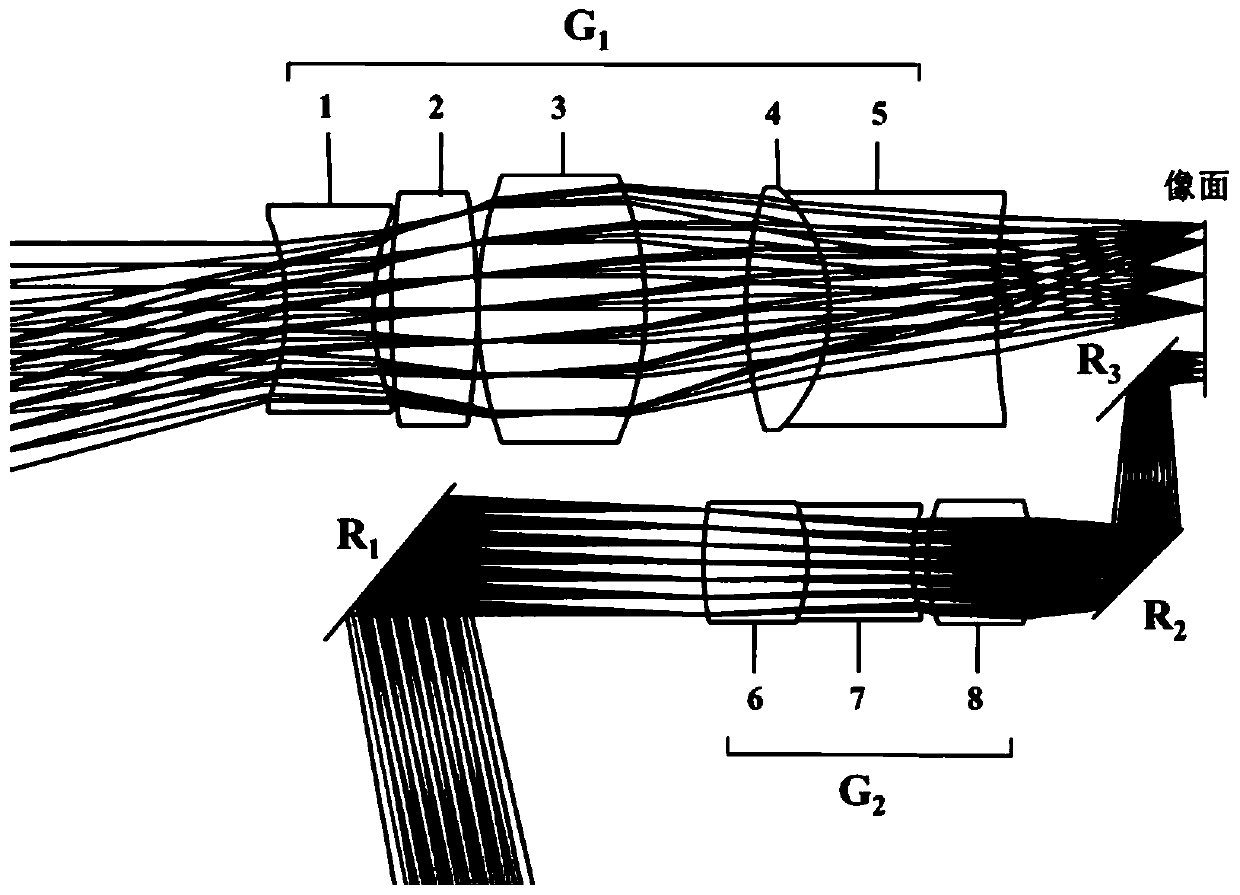
The invention discloses a bifocal bidirectional combined imaging optical system. The system comprises a short-focus lens group for forward observation, a long-focus lens group for lateral observationand a plane mirror group for turning a light path, wherein the short-focus lens group is composed of five-sheet four groups of lenses, and the long-focus lens group is composed of a double-glued lensgroup and a single lens, a plane mirror set is composed of three plane mirrors, one plane mirror is located on the left side of the long-focus lens group, and the other two plane mirrors are located on the right side of the long-focus lens group. The short-focus large-field-of-view lens group adopts a negative, positive, positive, positive and negative five-piece lens type structure, the focal power is reasonably distributed, the fourth lens and the fifth lens are combined to form the double-glued lens, so the structure is compact, correction of chromatic aberration and spherical aberration isfacilitated, and the imaging quality is greatly improved.

Description

technical field [0001] The present invention relates to the field of optical imaging, more specifically, to a bifocal bidirectional combined imaging optical system. Background technique [0002] Traditional optical lenses can only be used to observe objects in a single direction. In the scene of multi-directional observation, the cooperation of multiple sets of lenses is required, but it is difficult for multiple sets of lenses to achieve complete synchronization and coordination, and the combination of image planes is also relatively complicated, which greatly reduces the accuracy and speed requirements of automation instructions. [0003] For example, in traffic monitoring, the monoscopic camera has a single field of view for information acquisition and too little information, so it cannot intelligently and automatically judge whether the vehicle has violated traffic regulations. Being able to monitor vehicles at a fixed distance in a fixed scene greatly inhibits the deve...

Claims


Application Information

Patent Timeline
Patent Type & Authority Applications(China)
IPC IPC(8): G02B13/00G02B17/08G02B27/00H04N5/225
CPCG02B13/006G02B27/0025G02B17/08H04N23/55
Inventor 杨磊陈梦谢洪波杨鼎超杨童
Owner TIANJIN UNIV
Learn More