An electrical switch cabinet pressure relief device

A technology of electrical switch and pressure relief device, which is applied in the cooling/ventilation of substation/switchgear, details of substation/switch layout, substation/power distribution device shell, etc., which can solve the problems of low reliability, failure to open automatically, and bolt damage and other issues, to avoid injury to the staff, to ensure the effect of pressure relief, and to improve the effect of safety

Inactive Publication Date: 2021-06-15
HUNAN CITY UNIV
View PDF0 Cites 0 Cited by
  • Summary
  • Abstract
  • Description
  • Claims
  • Application Information

AI Technical Summary

Problems solved by technology

However, the reliability of bolts is not high. When a short-circuit fault occurs, the bolts may not be able to be destroyed, so that they cannot play the role of pressure relief; or, when the pressure is too high, the cover plate may be washed by high-pressure gas Going out will hurt the on-site personnel, and in some common pressure relief devices, a simple one-way valve or a cover plate is used, which cannot be opened automatically, and if it is opened too violently, it is easy to injure the external staff

Method used


Image

  • An electrical switch cabinet pressure relief device
  • An electrical switch cabinet pressure relief device
  • An electrical switch cabinet pressure relief device

Examples


Embodiment 1

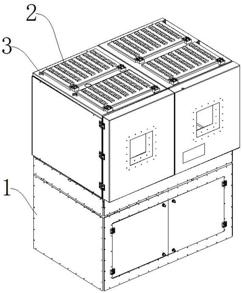
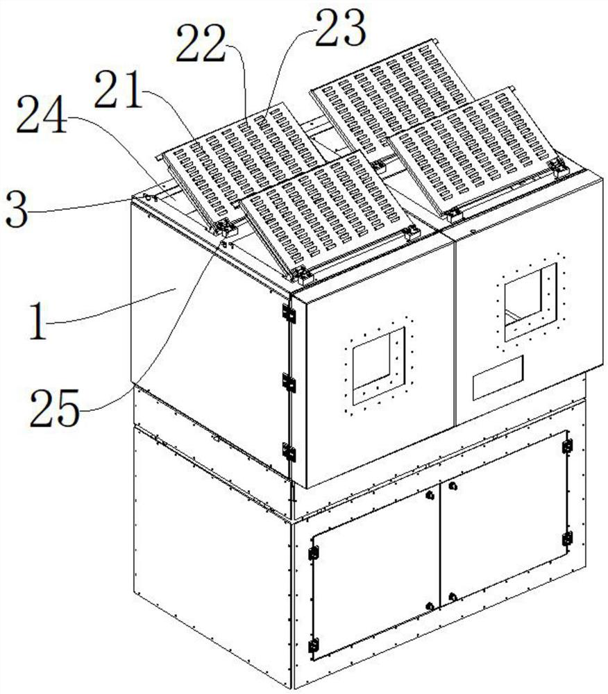
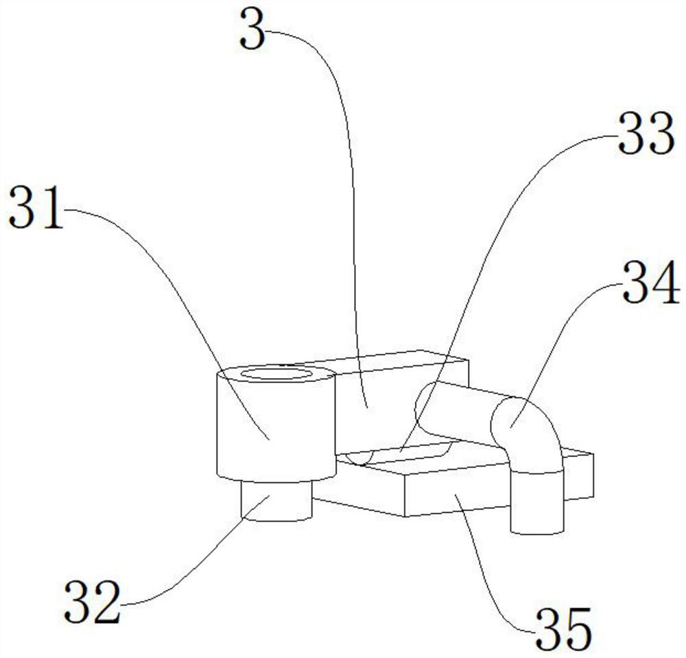
[0044] Such as Figure 1-Figure 6 As shown, the opening aid mechanism 4 includes a rotating plate 41, a universal joint 42, a pulling spring 43, and a detection switch 44. The rotating plate 41 is connected to the cover plate 21 of the pressure relief mechanism 2 by welding, and one end of the rotating plate 41 is connected to the universal joint 42. The universal joint 42 is connected to the electrical switch cabinet 1 through the pulling spring 43, and the other end of the rotating plate 41 is provided with a detection switch 44. When the locking mechanism 3 releases the pressure relief mechanism 2, the pulling spring 43 pulls the universal joint 42 and the rotating plate 41 , so that the cover plate 21 is flipped open, and the detection switch 44 is separated from the rotating plate 41 at the same time, thereby sending an alarm signal to the processor; Ventilation holes 22 are formed on the top, and the upper end of the cover plate 21 is connected to the arc-shaped plate 23...

Embodiment 2

[0047] Such as Figure 7 The difference between the present embodiment and embodiment 1 is that the opening-assisting mechanism 4 includes a rotating plate 41, a universal joint 42, a cylinder barrel 411, and a pulling cylinder 412, and the rotating plate 41 is connected to the cover plate 21 of the pressure relief mechanism 2 by welding, and the rotation One end of the plate 41 is connected to the universal joint 42, the other end of the rotating plate 41 is provided with a detection switch 44, the universal joint 42 is connected to the cylinder barrel 411, the inside of the cylinder barrel 411 is connected to the pulling cylinder 412, and the pulling cylinder 412 is connected to the electrical switch cabinet 1, and the cylinder The barrel 411 cooperates with the pulling cylinder 412. After the locking mechanism 3 releases the cover plate 21, the negative pressure inside the cylinder barrel 411 and the pulling cylinder 412 shrinks the cylinder barrel 411 and the pulling cylind...


PUM


Abstract

The invention discloses a pressure relief device for an electrical switchgear, which includes an electrical switchgear, and is characterized in that it also includes a pressure relief mechanism for pressure relief, an opening assisting mechanism for supporting the opening of the pressure relief mechanism, and a supporting The opening angle support mechanism of the pressure relief mechanism, the upper end of the electrical switch cabinet is connected to the pressure relief mechanism, the power end of the pressure relief mechanism is connected to the opening assisting mechanism, and the fixed end of the pressure relief mechanism is connected to the locking mechanism. The present invention utilizes the cooperation of the pressure relief mechanism, the locking mechanism and the opening-assisting mechanism, so that the locking mechanism can be opened in time when the internal pressure of the electrical switch cabinet is too high, and the pressure relief mechanism can be opened through the opening-assisting mechanism to ensure the pressure relief effect. The cooperation of mechanism, opening assisting mechanism and supporting mechanism can prevent the pressure relief mechanism from opening too large angle suddenly at one time, avoid injuring the staff, improve safety, use the opening assisting mechanism to adjust and automatically open the pressure relief mechanism, and can control the pressure relief The speed at which the mechanism opens.

Description

technical field [0001] The invention relates to the field of electrical switch cabinets, in particular to a pressure relief device for an electrical switch cabinet. Background technique [0002] The main function of the switchgear is to open and close, control and protect electrical equipment during the process of power generation, transmission, distribution and power conversion in the power system. The components in the switch cabinet are mainly composed of circuit breakers, disconnectors, load switches, operating mechanisms, transformers and various protection devices. There are many classification methods of switch cabinets. For example, according to the installation method of circuit breakers, it can be divided into removable switch cabinets and fixed switch cabinets; or according to the different cabinet structures, it can be divided into open switch cabinets, metal-enclosed switch cabinets, and metal Closed armored switchgear; according to different voltage levels, it...

Claims


Application Information

Patent Timeline
Patent Type & Authority Patents(China)
IPC IPC(8): H02B1/30H02B1/56
CPCH02B1/30H02B1/565
Inventor 杨京渝彭丽李立雄杨娴蔡振华
Owner HUNAN CITY UNIV
Why Eureka
Try Eureka