A digital beamforming terminal device for satellite communication
What is AI technical title?
AI technical title is built by Patsnap AI team. It summarizes the technical point description of the patent document.
A digital beam and terminal device technology, applied in satellite radio beacon positioning systems, measurement devices, radio wave measurement systems, etc., can solve the problems of bulky and complex equipment, limited array scale and number of beams, and large space occupation, etc., to achieve High degree of integration, reduced volume power consumption, and simple structure
Active Publication Date: 2021-10-22
NO 54 INST OF CHINA ELECTRONICS SCI & TECH GRP
View PDF12 Cites 0 Cited by
Summary
Abstract
Description
Claims
Application Information
AI Technical Summary
This helps you quickly interpret patents by identifying the three key elements:
Problems solved by technology
Method used
Benefits of technology
Problems solved by technology
[0003] Traditional analog phased array antennas implement phase-shifted beamforming at radio frequency, especially in applications requiring multiple beams, usually using a splitter combiner combined with a Butler matrix. The equipment is bulky and complex, cumbersome to debug, and is greatly affected by the external environment , Moreover, once the beam is determined, it cannot be changed, the array size and the number of beams are limited, and the side lobe index is also difficult to optimize, and adaptive beam zeroing cannot be realized, etc.
[0004] The traditional satellite communication user terminal station is usually an independent set of antenna equipment and terminal modem equipment, and the two are connected by optical fiber or radio frequency coaxial cable, which takes up a lot of space and the outline of the whole station is high
Method used
Image
Click on the blue label to locate the original text in one second.
Reading with bidirectional positioning of images and text.
Examples
Embodiment Construction
[0038] The present invention will be further described below in conjunction with the accompanying drawings and specific embodiments.
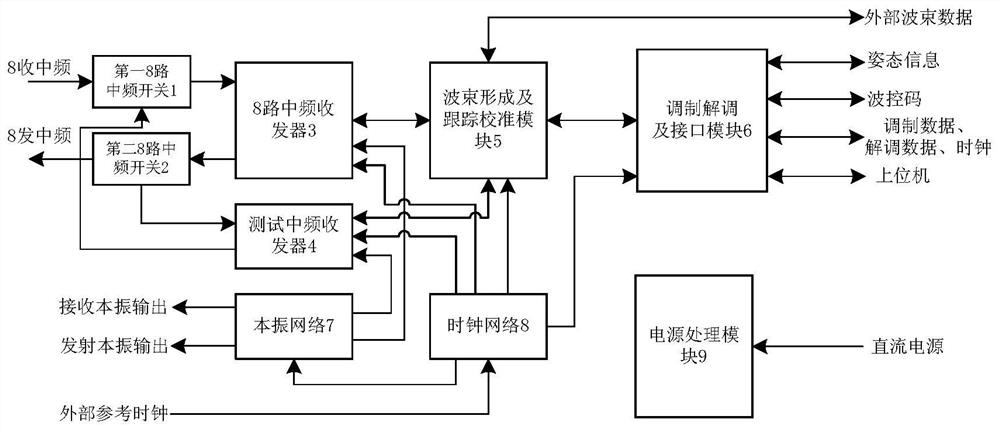
[0039] Such as figure 1 As shown, a digital beamforming terminal device for satellite communication, which includes a first 8-way IF switch 1, a second 8-way IF switch 2, an 8-way IF transceiver 3, a test IF transceiver 4, and a power processing unit 9 , beamforming and tracking calibration module 5, modulation and demodulation and interface module 6, local oscillator network 7, clock network 8;
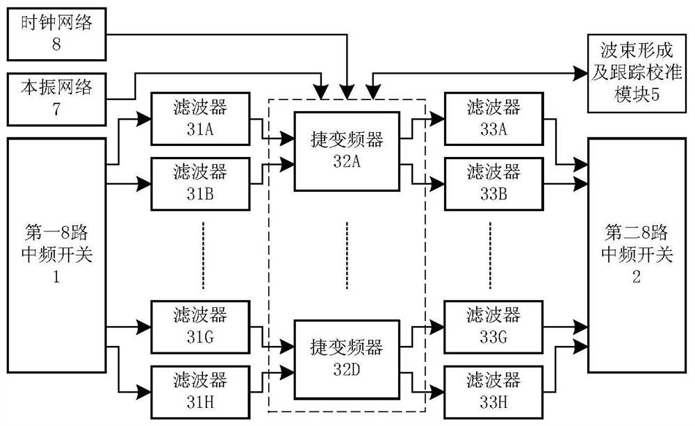
[0040] Among them, in the receiving chain, after the 8-way IF receiving signal and the test calibration IF signal are switched and selected by the first 8-way IF switch 1, they enter the 8-way IF transceiver 3 to complete I / Q quadrature mixing and digital processing. The preprocessed data is sent to the beamforming and tracking calibration module 5 to complete timing synchronization of 8-way I / Q signals, channel amplitude phase calibration, beamformi...
PUM
Abstract
The invention relates to a digital beam forming terminal device for satellite communication, and belongs to the technical field of digital beam forming. It includes the first IF switch, the second IF switch, 8-way IF transceiver, test IF transceiver, beamforming and tracking calibration module, modulation and demodulation and interface module, local oscillator network, clock network, power processing and other components, it Through the first IF switch, the second IF switch, the 8-way IF transceiver, and the test IF transceiver, the 8-channel signal or calibration signal is sent to the beamforming and tracking calibration module, modulation and demodulation and interface module for processing, so as to realize zero-adjustment impedance Interference beamforming and carrier signal demodulation; the transmitting end is opposite to the receiving process, completes the data modulation, forms a specific directional beam and transmits. The invention can conveniently realize the functions of amplitude and phase calibration, multi-beam adjustment, side lobe weight optimization, and self-adaptive beam zero adjustment, and has the characteristics of high integration, simple structure, high reliability, convenient scale expansion and the like.
Description
technical field [0001] The invention belongs to the technical field of digital beam forming (Digital Beam Forming, DBF), in particular to a digital beam forming terminal device for satellite communication. Background technique [0002] Because of its small size, low loss, low profile, easy beam zeroing, beam forming, multi-beam, and quick adjustment of beam pointing, active phased array antennas have been used in satellite communication systems for more than ten years. Both the space segment and the user terminal are widely used. [0003] Traditional analog phased array antennas implement phase-shifted beamforming at radio frequency, especially in applications requiring multiple beams, usually using a splitter combiner combined with a Butler matrix. The equipment is bulky and complex, cumbersome to debug, and is greatly affected by the external environment , Moreover, once the beam is determined, it cannot be changed, the array size and the number of beams are limited, the ...
Claims
Application Information
Patent Timeline
Application Date:The date an application was filed.
Publication Date:The date a patent or application was officially published.
First Publication Date:The earliest publication date of a patent with the same application number.
Issue Date:Publication date of the patent grant document.
PCT Entry Date:The Entry date of PCT National Phase.
Estimated Expiry Date:The statutory expiry date of a patent right according to the Patent Law, and it is the longest term of protection that the patent right can achieve without the termination of the patent right due to other reasons(Term extension factor has been taken into account ).
Invalid Date:Actual expiry date is based on effective date or publication date of legal transaction data of invalid patent.

