Magnetic devices, systems, and methods

A magnetic component and magnetic coupling technology, used in medical science, surgery, wound clips, etc., can solve the problem of high sensitivity to differences in tissue thickness, not suitable for patients of different sizes and ages, and not suitable for different types of tissue anastomosis, etc. question

Pending Publication Date: 2020-04-17
RGT UNIV OF CALIFORNIA
View PDF10 Cites 0 Cited by
  • Summary
  • Abstract
  • Description
  • Claims
  • Application Information

AI Technical Summary

Problems solved by technology

Some existing methods may not work well for patients of different sizes and ages
Also, while some existing methods are capable of forming an anastomosis on one type of tissue, they may not be well suited to anastomosis on a different type of tissue
Attractive forces between magnetic pairs generally decrease with distance, and existing methods may be more sensitive to differences in tissue thickness than ideal
In addition, at least some existing magnetic methods for forming anastomoses may not be well suited for readily available surgical instruments and may be more complex than ideal
[0008] Existing methods and devices for delivering magnets to the target site may be less than ideal, and in at least some cases, the size of the incision and surgical access to the anastomotic site are not ideally addressed by existing methods
Also, with at least some existing methods, the placement of the magnetic member at the desired target location may be less than ideal

Method used


Image

  • Magnetic devices, systems, and methods
  • Magnetic devices, systems, and methods
  • Magnetic devices, systems, and methods

Examples


Embodiment approach 1

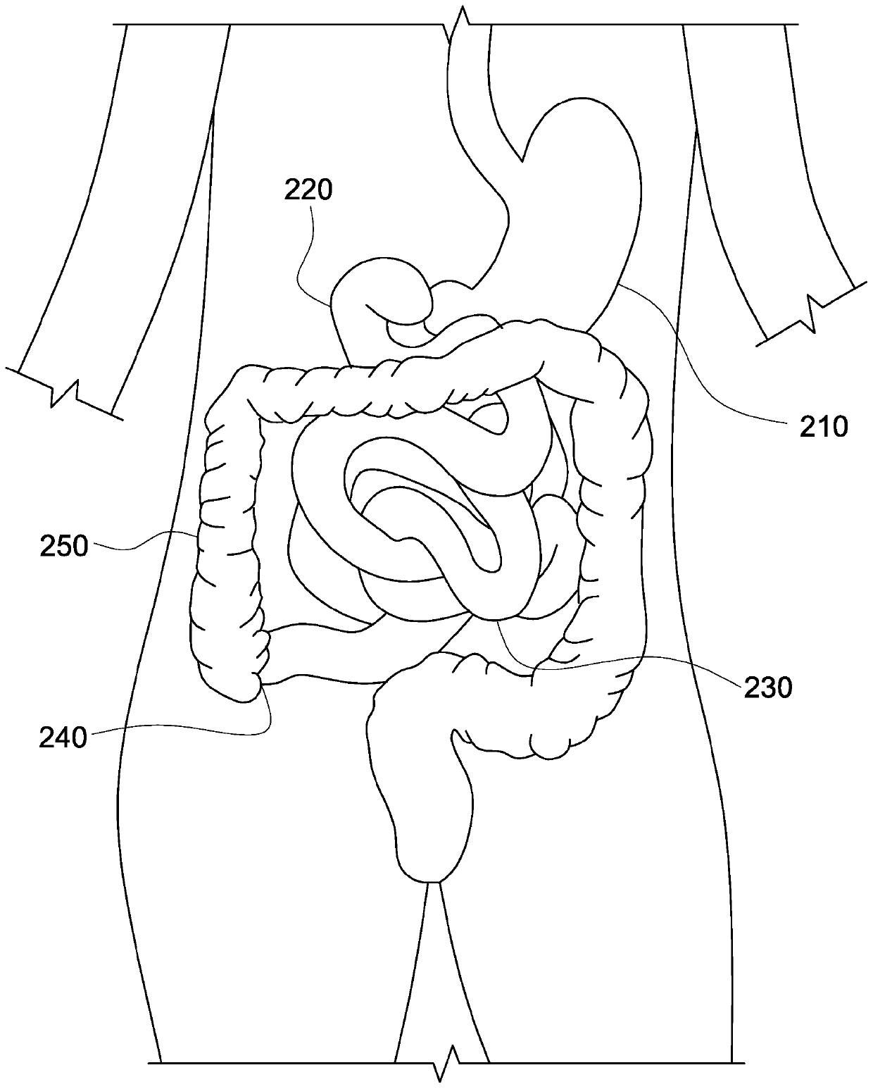
[0166] Embodiment 1: A system for forming a side-to-side anastomosis in a gastrointestinal tract of a patient, the system comprising: a first magnetic member configured adjacent a first magnetic member at a first location along the gastrointestinal tract a luminal tissue region positioned; and a second magnetic member configured to be positioned adjacent to the second luminal tissue region at a second location along the gastrointestinal tract, wherein: the first and second magnetic members are configured be attracted to each other with a force of at least about 6 N when engaged with each other (with the first and second luminal tissue regions interposed therebetween), so that the first and second luminal tissue regions are brought together and causing necrosis in portions of the first and second luminal tissue regions while forming the anastomosis between the first and second luminal tissue regions, and the first and second magnetic members are configured to The first and seco...

Embodiment approach 2

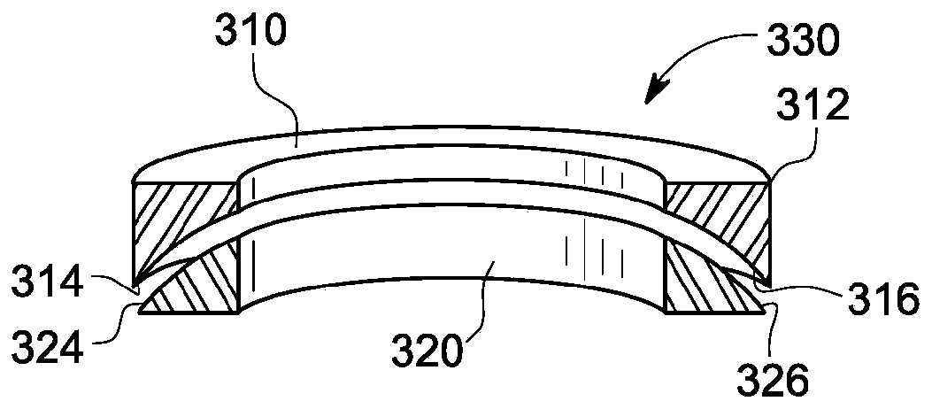
[0167] Embodiment 2: The system of Embodiment 1, wherein the first magnetic member includes a first engagement surface, and the second magnetic member includes a surface relative to the first magnetic member when magnetically aligned with the first magnetic member. A second engaging surface with an inclined engaging surface.

Embodiment approach 3

[0168] Embodiment 3: The system of Embodiment 2, wherein the first engagement surface and the second engagement surface each have a shape profile sized to be between the first engagement surface and the second engagement surface. A gap is provided between portions of the second engaging surface, the gap being in the range of about 0.65 mm to about 0.85 mm when the other portions of the first engaging surface and the second engaging surface are in contact with each other.


PUM


Abstract

Methods and apparatus for safely forming anastomoses comprise magnetic members configured to accommodate different tissue types and patients of differing size and weight. The magnetic members may comprise first and second magnetic members configured to engage each other with a force sufficient to form anastomosis while taking a sufficiently long time to allow the intestinal walls to fuse together.The first and second magnetic members can be configured to form anastomoses between both similar and different types of intestinal tissue. An elongate surgical placement instrument can be configuredto engage and manipulate the first and second magnet members through the intestinal wall from outside the intestinal wall in order to place each of the magnetic members at desired locations.

Description

[0001] Cross References to Related Applications [0002] Pursuant to 35 U.S.C. §119(e), this application claims priority to U.S. Provisional Patent Application No. 62 / 527,690, filed June 30, 2017, which is hereby incorporated by reference in its entirety for all purposes. [0003] statement of government support [0004] This invention was made with Government support under Contract P50 FD003793 awarded by the FDA Pediatric Devices Alliance. The government has certain rights in this invention. technical field [0005] The present invention relates to magnetic devices, systems and methods for forming an anastomosis. Background technique [0006] Anastomosis in biological systems can refer to the formation of a connection between two biological tissues or structures. Biological anastomoses can occur between tubular biological structures, such as blood vessels or loops of intestine. Bowel anastomosis can be achieved surgically by removing a section of bowel and joining t...

Claims


Application Information

Patent Timeline
Patent Type & Authority Applications(China)
IPC IPC(8): A61B17/00A61B17/08A61B17/10A61B17/11
CPCA61B17/1114A61B2017/00477A61B2017/00876A61B2017/1117A61B2017/1139A61B2017/1107A61B2017/1132A61B2017/1135
Inventor M·R·哈里森D·A·奎亚特R·J·费克特
Owner RGT UNIV OF CALIFORNIA
Why Eureka
Try Eureka