
Floor nozzle for a vacuum cleaner

A technology for vacuum cleaners and floors, which is applied in the direction of vacuum cleaners, suction nozzles, household appliances, etc. It can solve the problem that coarse dirt particles do not reach the suction air flow, and achieve a good suction effect

Active Publication Date: 2020-04-21
威赛有限公司
View PDF5 Cites 0 Cited by
  • Summary
  • Abstract
  • Description
  • Claims
  • Application Information

AI Technical Summary

Problems solved by technology

A frequent problem here is that coarse dirt particles are pushed in front of the floor nozzle of the vacuum cleaner and do not reach the effective suction air flow
Neither method is suitable for carpeted floors

Method used


Image

  • Floor nozzle for a vacuum cleaner
  • Floor nozzle for a vacuum cleaner
  • Floor nozzle for a vacuum cleaner

Examples


Embodiment Construction

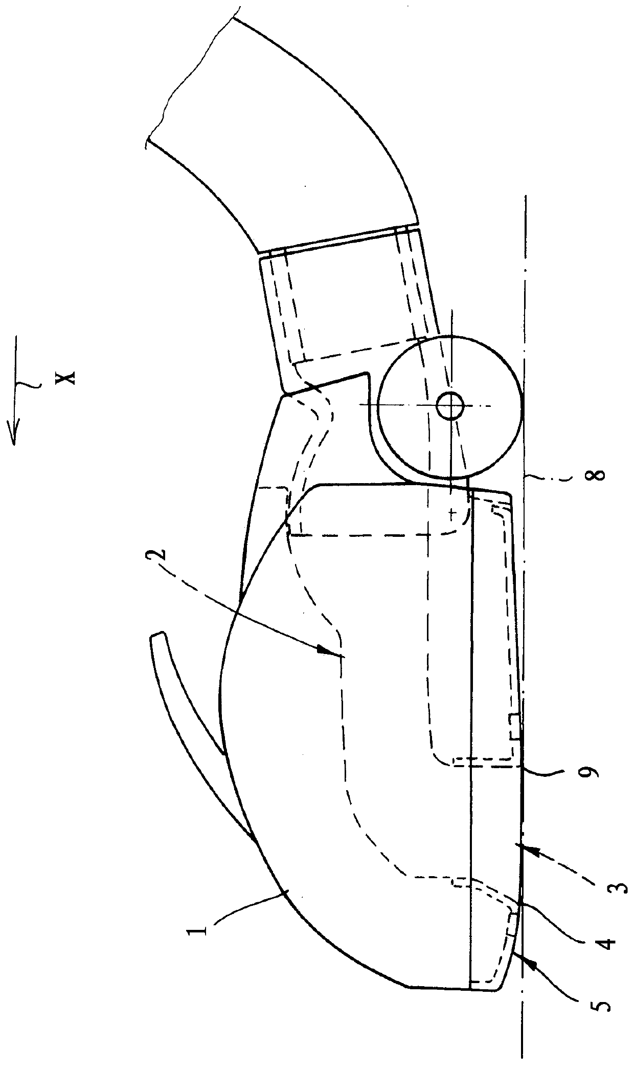
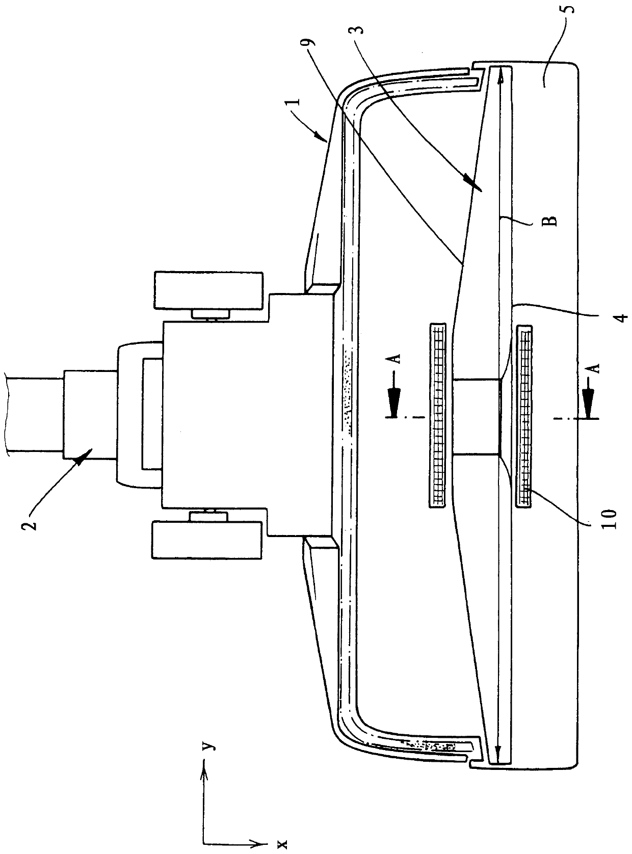
[0023] exist figure 1 and 2 The basic structure of the floor nozzle of the vacuum cleaner can be seen in : The floor nozzle of the vacuum cleaner has a housing 1 extending in the working direction x and in a transverse direction y perpendicular to the working direction and a Suction opening 3 on guide 2. The suction opening 3 extends across a width B in the transverse direction y and is delimited in the working direction x by a front suction opening edge 4 and a rear suction opening edge 9 .

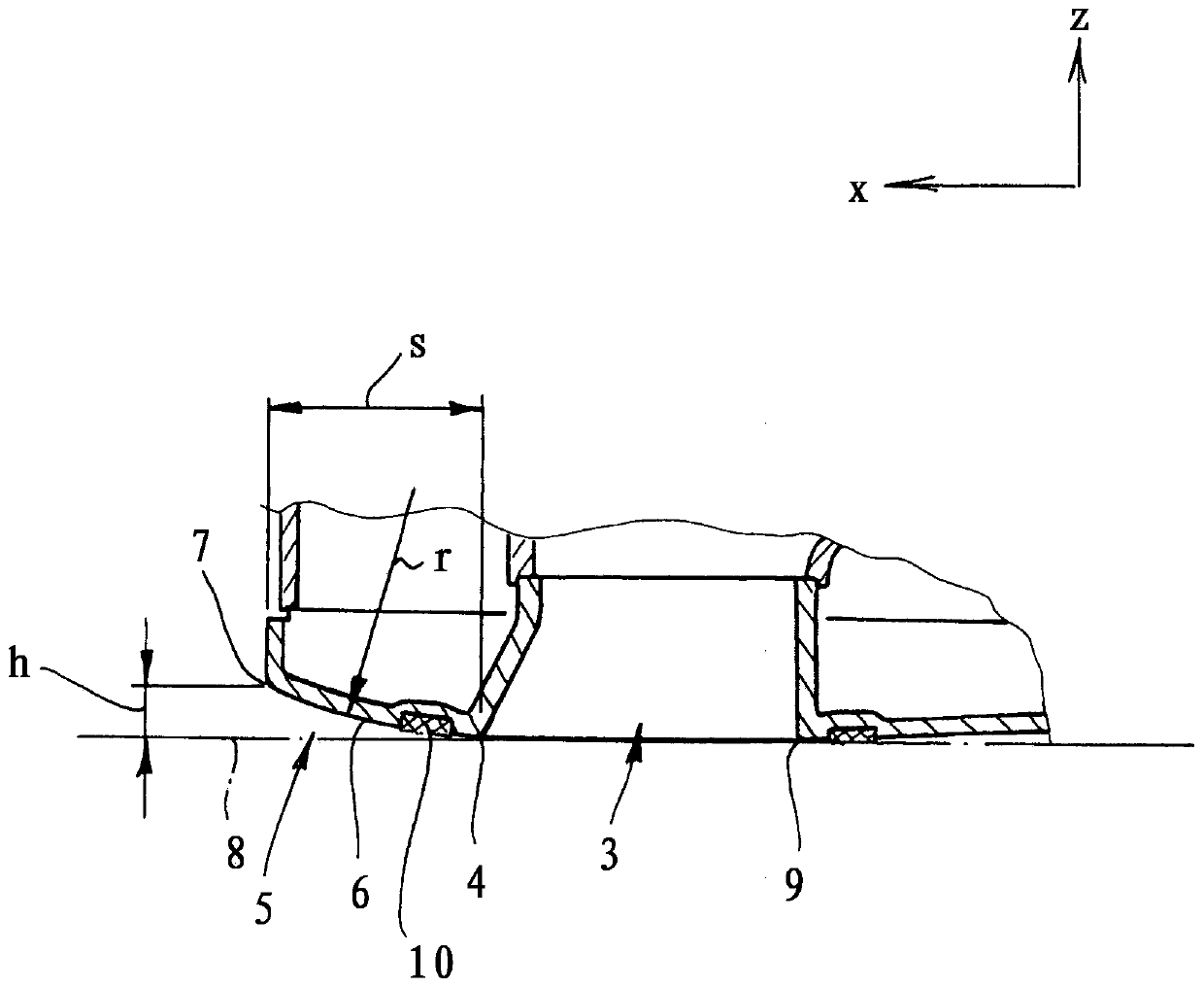
[0024] According to the invention, a sliding surface 5 is provided in front of the front suction opening edge 4 which extends in the transverse direction y over at least 75% of the width B of the suction opening 3 . sliding surface 5 in Figure 3A In the longitudinal section shown, along the working direction x, there is a circular segment 6 whose radius of curvature r is between 40 mm and 80 mm. Along the working direction x, the sliding surface 5 extends over a length s of at least...


PUM


Abstract

The invention relates to a vacuum cleaner nozzle comprising a housing (1) extending in a working direction (x) and a transverse direction (y) perpendicular to the working direction and a suction opening (3) which is arranged on the housing (1) at the lower side and can be connected to a suction gas guide (2). The suction opening extends in the transverse direction (y) in the width (B) and is delimited in the working direction (x) by a front suction opening edge (4) and a rear suction opening edge (9). According to the invention, a sliding surface (5) is provided in front of the front suction opening edge (4) in the working direction (x), said sliding surface extending in the transverse direction (y) over at least 75% of the width (B) of the suction opening (3). The sliding surface (5) has,in a longitudinal section, an arc segment (6) with a radius of curvature (r) of between 40 mm and 80 mm. The sliding surface (5) has an extension length (s) of at least 15 mm in the working direction(x).

Description

technical field [0001] The invention relates to a vacuum cleaner floor nozzle with a housing extending in a working direction and in a transverse direction perpendicular to the working direction, and a suction opening arranged on the housing on the underside and connectable to a suction air guide. The suction opening extends across the width in the transverse direction and is delimited in the working direction by a front suction opening edge and a rear suction opening edge. Background technique [0002] The vacuum cleaner floor nozzle is used to form and guide the suction air flow of the vacuum cleaner. The design of a vacuum cleaner floor nozzle significantly affects the cleaning performance of a vacuum cleaner system. The geometric design of the floor nozzle of the vacuum cleaner thus determines the width of the gap through which the suction air flow entering the vacuum cleaner is guided along the surface to be cleaned. This results in very specific flow and vacuum condi...

Claims


Application Information

Patent Timeline
Patent Type & Authority Applications(China)
IPC IPC(8): A47L9/02A47L9/00
CPCA47L9/02A47L9/00
Inventor P·拉特K-D·里尔
Owner 威赛有限公司
Learn More