Yarn winding equipment

A technology for coiling equipment and yarn, which is applied in the field of yarn coiling equipment, and can solve the problems of reducing the processing efficiency of the bobbin processing device, moving the tray, and not moving.

Active Publication Date: 2022-07-12
MURATA MASCH LTD
View PDF11 Cites 0 Cited by
  • Summary
  • Abstract
  • Description
  • Claims
  • Application Information

AI Technical Summary

Problems solved by technology

In this way, for example, the following problem is likely to occur, that is, in the vicinity of the point where the separate path and the discharge path merge, the discharge tray conveyed on the separate path and the discharge tray conveyed on the discharge path are pressed against each other and cannot move ( bridge plug phenomenon)
In such a case, the discharge tray cannot be conveyed to the bobbin processing device side, and the processing efficiency of the bobbin processing device can be reduced.
In addition, if the discharge path is congested, the tray cannot move from the individual path to the discharge path, and the individual path is blocked, the tray cannot be discharged from the winding unit, and there is a possibility that the processing of the winding unit will stop.
[0007] In addition, even with the configuration in which the bypass path as described above is provided in the pallet conveyance device, if the discharge trays are congested on the discharge path, there will be problems such as blockage of the discharge tray at the confluence position where the discharge path and the bypass path merge.

Method used


Image

  • Yarn winding equipment
  • Yarn winding equipment
  • Yarn winding equipment

Examples


Embodiment Construction

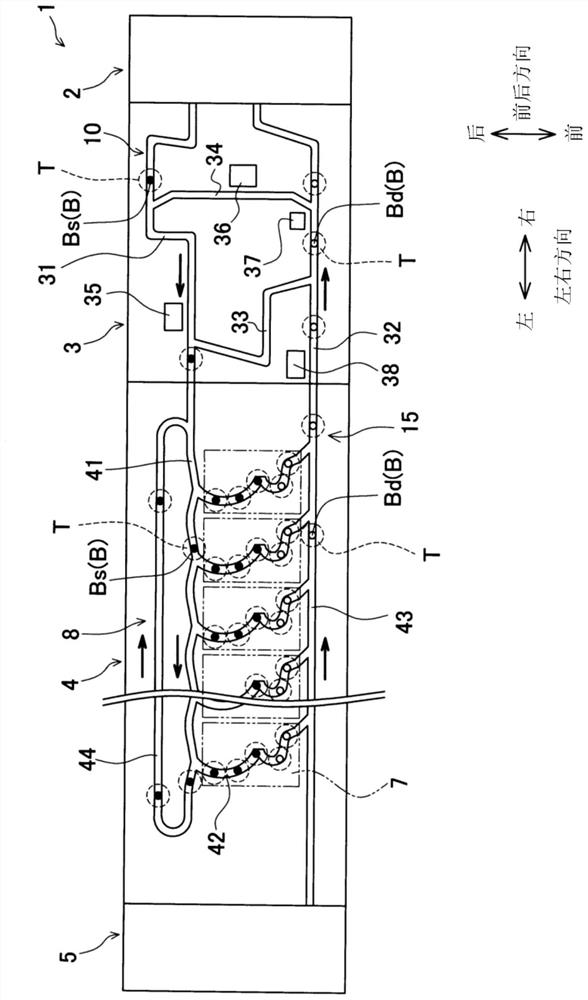
[0044] Next, refer to Figure 1 to Figure 10 Embodiments of the present invention will be described. In addition, for the convenience of description, the figure 1 The directions shown are set as the front-rear direction and the left-right direction. Let the direction (vertical direction) of the gravitational force acting orthogonal to both the front-rear direction and the left-right direction be the vertical direction.

[0045] (Outline Structure of Yarn Winding Equipment)

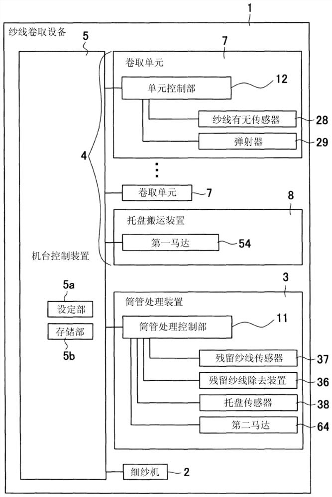
[0046] First, use figure 1 and figure 2 The schematic configuration of the yarn winding device 1 according to the present embodiment will be described. figure 1 It is a schematic plan view of the yarn winding device 1 according to the present embodiment. figure 2 It is a block diagram showing the electrical configuration of the yarn winding apparatus 1 . like figure 1 As shown, the yarn winding device 1 includes a spinning frame 2 , a bobbin processing device 3 , a winder 4 , and a machine contro...


PUM


Abstract

The present invention provides a yarn winding apparatus including a plurality of winding units, a tray conveying device having an individual path and a first discharge path, a bobbin processing device having a second discharge path, and a control unit. The pallet conveying device has a first conveyor mechanism that conveys the pallets on the first discharge path. The bobbin processing apparatus has a second conveyor mechanism that conveys the trays on the second discharge path. The first conveyor mechanism and the second conveyor mechanism are driven by separate drive sources, respectively. The yarn winding device further includes: a tray detection unit that detects the tray on the second discharge path; and a determination unit that determines whether the tray remains on the second discharge path based on the detection result of the tray detection unit. When the determination unit determines that the tray remains on the second discharge path, the control unit stops the operation of the first conveyor mechanism while operating the second conveyor mechanism.

Description

technical field [0001] The present invention relates to a yarn winding device. Background technique [0002] The yarn winding apparatus disclosed in Japanese Patent Laid-Open No. 2011-20837 includes a plurality of winding units, a bobbin preparation device (hereinafter referred to as a bobbin processing device), and a pallet conveying device. Each winding unit unwinds the yarn wound on the pre-supply bobbin and winds it on the winding bobbin. The bobbin processing device performs preparation of pre-supply bobbins to be supplied to a plurality of winding units, residual yarn removal processing of pre-supply bobbins (hereinafter referred to as discharge bobbins) discharged from the plurality of winding units, and the like. The pallet conveying device conveys the pallet (yarn feeding pallet) on which the pre-supply bobbin is mounted and the pallet (discharge pallet) on which the discharge bobbin is mounted, and transfers the pallets between the bobbin handling device and the p...

Claims


Application Information

Patent Timeline
Patent Type & Authority Patents(China)
IPC IPC(8): B65H54/54B65H67/04B65H67/06B65H73/00
CPCB65H54/54B65H67/0405B65H67/069B65H73/00B65H2701/31B65H67/06
Inventor 平井克尚平野敬士梅冈利成
Owner MURATA MASCH LTD
Why Eureka
Try Eureka