Die cutting machine for printing

A technology of die-cutting machine and die-cutting plate, which is applied in metal processing and other directions, can solve the problems of low die-cutting quality and poor precision, and achieve the effect of improving die-cutting quality

Inactive Publication Date: 2022-05-06
无锡天辰技贸发展有限公司
View PDF0 Cites 0 Cited by
  • Summary
  • Abstract
  • Description
  • Claims
  • Application Information

AI Technical Summary

Problems solved by technology

However, each time the die-cutting plate is replaced, the die-cutting plate needs to be manually positioned, and the accuracy of manual positioning is poor, resulting in low die-cutting quality

Method used


Image

  • Die cutting machine for printing
  • Die cutting machine for printing
  • Die cutting machine for printing

Examples


Embodiment Construction

[0031] The following is attached Figure 1-5 The application is described in further detail.

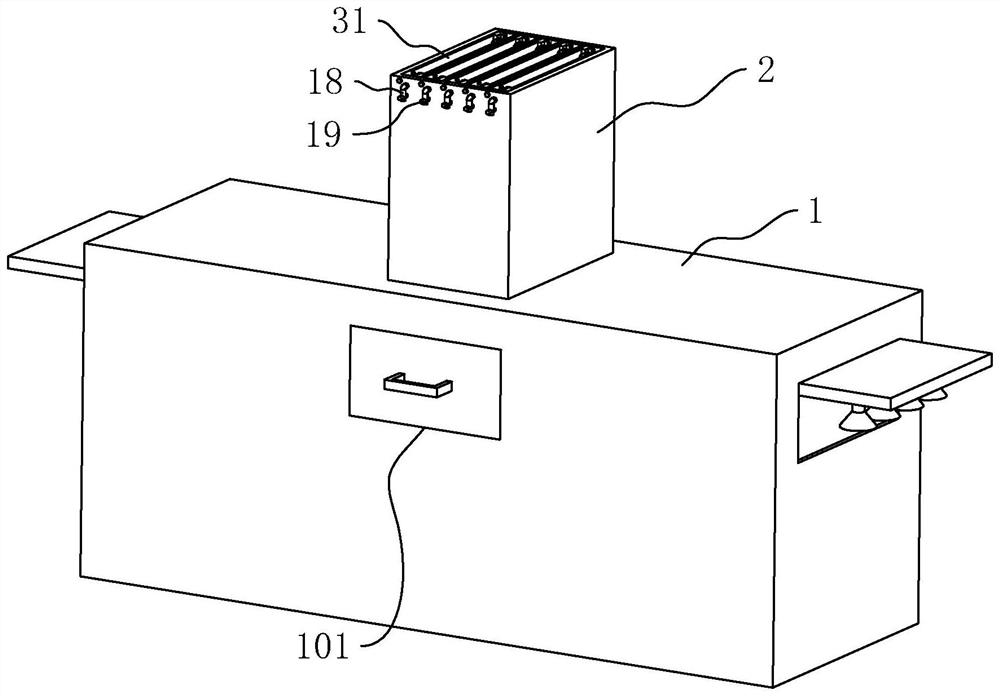
[0032] The embodiment of the present application discloses a printing die-cutting machine. refer to figure 1 , figure 2 and image 3 , The die-cutting machine for printing includes a body 1, one end of the body 1 in the length direction is a feed end, and the other end is a discharge end.

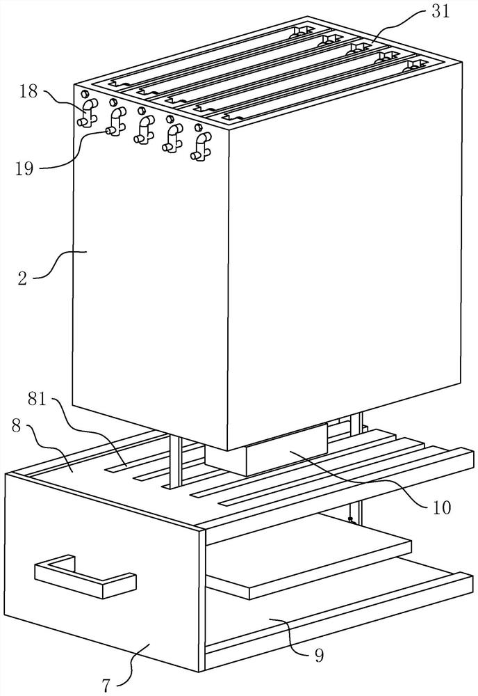
[0033] The top of the machine body 1 is connected with a plate storage box 2 with a hollow interior and an open top. Multiple die-cutting components are arranged in the plate storage box 2, and the multiple die-cutting components are evenly arranged along the direction from the feeding end to the discharging end. , Different die-cutting components are used to die-cut different products.

[0034] The die-cutting assembly includes an installation box 31 bolted in the plate storage box 2 , and a die-cutting plate 32 located in the installation box 31 . The inside of the installation box 31 is ...


PUM


Abstract

The invention relates to the field of cutting equipment, in particular to a printing die-cutting machine which comprises a machine body, a hollow plate storage box is communicated with the upper portion of the machine body, a plurality of hollow mounting boxes with the tops and the bottoms open are arranged in the plate storage box, and lifting grooves with the bottoms closed are vertically formed in the two opposite inner side walls of each mounting box; lifting blocks are arranged in the lifting grooves in a sliding mode, lifting columns are arranged on the sides, back on to the lifting grooves, of the lifting blocks, compression springs are arranged between the lifting blocks and the groove bottoms of the corresponding lifting grooves in a supporting mode, and die cutting plates are arranged in the mounting boxes in a sliding mode and rotationally connected between the two corresponding lifting columns. An access hole is formed in the position, opposite to the lower portion of the plate storage box, of one side of the machine body, a support is arranged on the support in a sliding mode, a supporting plate used for supporting printed materials is arranged on the support, a bearing plate is further arranged on the position, opposite to the upper portion of the supporting plate, of the support, and receding grooves are formed in the positions, opposite to the lifting columns, of the bearing plate. The die cutting device has the advantage of improving the die cutting quality.

Description

technical field [0001] The invention relates to the field of cutting equipment, in particular to a die-cutting machine for printing. Background technique [0002] Die-cutting machine is the most commonly used equipment in the packaging and printing industry. It is to use a die-cutter to form a die-cutting plate according to the pattern required by the product design. Under the action of pressure, the printed matter or other blanks are cut into the desired shape or cut marks. [0003] A numerically controlled die-cutting machine in the related art can be adapted to die-cutting processes of different products by replacing different die-cutting plates. However, each time the die-cutting plate is replaced, the die-cutting plate needs to be manually positioned, and the accuracy of manual positioning is poor, resulting in low die-cutting quality. Contents of the invention [0004] In order to improve the die-cutting quality of the die-cutting machine, the application provides ...

Claims


Application Information

Patent Timeline
Patent Type & Authority Applications(China)
IPC IPC(8): B26F1/38B26D7/26B26D7/00
CPCB26F1/38B26D7/26B26D7/00B26D2007/2607B26D2007/0012
Inventor 段黎睿
Owner 无锡天辰技贸发展有限公司
Why Eureka
Try Eureka