Agricultural small ridger

A ridge machine, a small technology, is used in agricultural machinery and implements, applications, agriculture, etc., and can solve the problems of lack of a convenient connection mechanism between a ridge plate and a support plate, reduced ridge quality, and inconvenient removal and cleaning of the ridge plate.

Inactive Publication Date: 2021-09-10
XUZHOU TIANYUANLE AGRI MACHINERY MFG CO LTD
View PDF11 Cites 0 Cited by
  • Summary
  • Abstract
  • Description
  • Claims
  • Application Information

AI Technical Summary

Problems solved by technology

[0005] In order to make up for the deficiencies of the existing technology and solve the problem of the lack of a convenient connection mechanism between the ridging plate and the support plate, which makes it inconvenient to disassemble the ridging plate for cleaning and reduce the quality of ridging, the present invention proposes a small agricultural ridging machine

Method used


Image

  • Agricultural small ridger
  • Agricultural small ridger
  • Agricultural small ridger

Examples


Embodiment 1

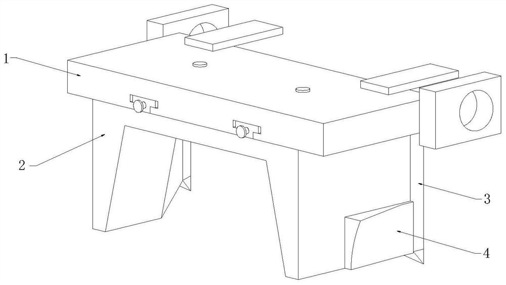
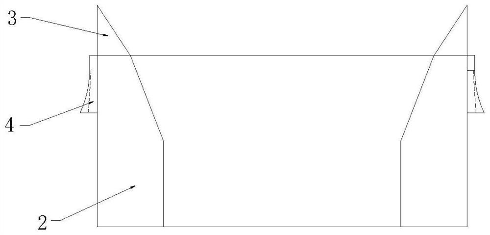
[0027] see Figure 1-4 Shown, a kind of agricultural small-sized ridging machine comprises support plate 1, ridging plate 2, plow point bar 3, soil turning plate 4 and connecting mechanism; Described support plate 1 bottom middle is installed with ridging plate 2, so The rear end of the ridging plate 2 is symmetrically installed with two plow point rods 3, and the top of the plow point rod 3 is attached to the bottom end of the support plate 1, and the lower sides of the left and right ends of the ridging plate 2 are fixedly installed with soil turning boards. 4;

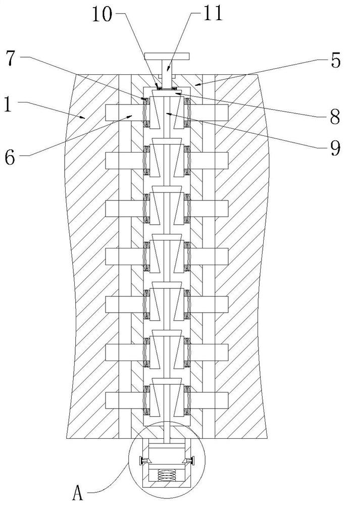
[0028] The connecting mechanism includes a T-shaped hollow rod 5, a T-shaped inclined block 6, a spring 7, a tapered block 8, a connecting rod 9 and a spring 2 10, and two T-shaped hollow rods are symmetrically fixed on the top of the ridging plate 2 5. Two T-shaped slots are arranged symmetrically at the bottom of the support plate 1, and a T-shaped empty bar 5 is installed inside the T-shaped slot, and more than ...

Embodiment 2

[0037] see Figure 5 As shown, compared with Example 1, as another embodiment of the present invention, a spring 5 20 is fixedly installed at the middle position of the inner top of the T-shaped slot, and a pointed cone block 19 is fixedly installed at the bottom of the spring 5 20. The top of the T-shaped empty bar 5 is provided with a draw-in groove, the bottom end of the pointed cone block 19 extends to the inside of the draw-in groove, the top of the support plate 1 is equipped with a T-shaped magnetic block 21, and the bottom end of the T-shaped magnetic block 21 extends to T The inside of the type groove is fixedly installed on the top of the pointed cone block 19; during work, when the T-shaped hollow rod 5 slides inside the T-shaped groove, the T-shaped empty rod 5 squeezes the pointed cone block 19, and the pointed cone block 19 Squeezed to move and squeeze the spring 5 20, when the pointed cone block 19 is aligned with the card slot, under the action of the spring fo...


PUM


Abstract

The invention belongs to the field of ridgers, and particularly relates to an agricultural small ridger which comprises a supporting plate, a ridging plate, a plough tip rod, a soil turning plate, a T-shaped hollow rod, a T-shaped inclined block, a first spring, conical blocks, a connecting rod, a second spring, a fastening bolt, a square plate, a square cylinder, a third spring, a pressing plate, an inclined block, a T-shaped block, a fourth spring, a pointed cone block, a fifth spring and a T-shaped magnetic block. The T-shaped hollow rod is inserted into a T-shaped groove, one end of the T-shaped inclined block is aligned with a limiting hole, then the fastening bolt is screwed, the fastening bolt moves along a nut, the fastening bolt moves to drive the conical block at the foremost end to move, then other conical blocks are driven to move through a connecting rod, the conical blocks move to extrude the T-shaped inclined block, the T-shaped inclined block moves to enter the limiting hole, and then the T-shaped hollow rod is clamped in the T-shaped groove, so that connection of the ridging plate and the supporting plate is completed.

Description

technical field [0001] The invention relates to the field of ridging machines, in particular to a small agricultural ridging machine. Background technique [0002] The ridging machine is mainly suitable for field ridging operations of potatoes, beans, and vegetables. The ridging machine has the characteristics of easy adjustment of ridge distance, ridge height, ridge row number, and angle, wide supporting range, and strong adaptability. . [0003] It is inconvenient for the ridging machine to turn over the soil on the side during the ridging process, causing the soil to be easily scattered in the gully between the ridges, resulting in insufficient ridging height. [0004] There are certain defects in the currently used ridging machines, such as the lack of a convenient connection mechanism between the ridging plate and the support plate, which makes it inconvenient to disassemble the ridging plate for cleaning and reduce the quality of ridging. Therefore, a kind of agricul...

Claims


Application Information

Patent Timeline
IPC IPC(8): A01B13/02A01B49/02
CPCA01B13/02A01B49/02
Inventor 宗海侠
Owner XUZHOU TIANYUANLE AGRI MACHINERY MFG CO LTD
Why Eureka
Try Eureka