
A smart manhole cover

A well cover and intelligent technology, applied in waterway systems, buildings, water supply devices, etc., can solve the problems of inconvenient opening of leakage holes, inconvenient discharge, and excessive water flow, so as to avoid waterlogging and accelerate water release

Active Publication Date: 2020-12-01
NINGBO LINGTONG TELECOM EQUIP
View PDF1 Cites 0 Cited by
  • Summary
  • Abstract
  • Description
  • Claims
  • Application Information

AI Technical Summary

Problems solved by technology

[0003] In the case of heavy rain in the city, the water on the road surface is drained through the manhole cover. When the manhole cover is blocked, the water drainage is not timely and it is easy to cause waterlogging. The existing patent application number is 201721249221.8. Intelligent manhole cover with anti-waterlogging function. In this document, when the liquid level at the manhole cover is detected to be too high by setting a liquid level sensor, the motor set at the bottom of the manhole cover is started to drive the screw to move, so that the baffle on the top of the screw and the leakage of the manhole cover The liquid hole connection is to open the leakage hole on the well cover for liquid leakage. However, since the general urban manhole cover is designed as a circle, the movement direction of the screw can be opened through this method, but it is inconvenient to open the leakage hole at the circumference. At the same time When there are obstacles such as branches and soil blocks on the top of the manhole cover, it is inconvenient to discharge. For the blockage on the surface of the manhole cover, there is still a lot of water flow and it is inconvenient to discharge. Therefore, we have proposed a smart manhole cover. For this reason, we have proposed an intelligent manhole cover. manhole cover

Method used


Image

  • A smart manhole cover
  • A smart manhole cover
  • A smart manhole cover

Examples


specific Embodiment approach

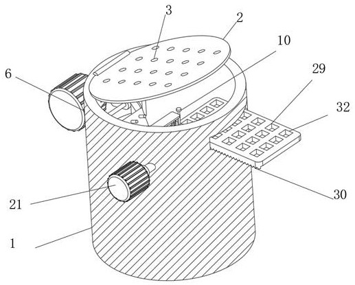
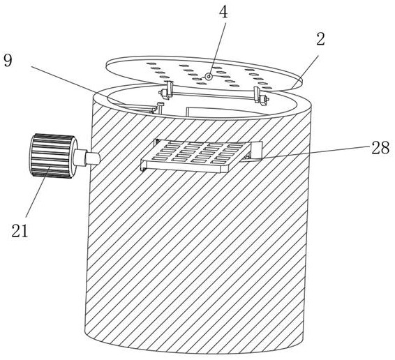
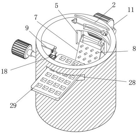
[0028]Specific embodiments: when it rains in the city, after water accumulation is formed at the top of the well cover body 2, the liquid level sensor 4 at the bottom of the well cover body 2 senses the liquid level at the top of the well cover body 2, starts the first motor 11, and then starts the first motor 11 Under the output power of the driving cam plate 13, the driving cam plate 13 starts to rotate. Since the driving cam plate 13 is in contact with the driven cam plate 12, under the action of the driving cam plate 13, the driven cam plate 12 is pressed and rotated in the opposite direction, thereby driving the rotating rod 14. Rotate, because dredging plate 7 is connected with rotating rod 14 by connecting plate 15, under the situation that rotating rod 14 direction rotates, dredging plate 7 rotates to well wall 1 top position from well wall 1 bottom, this moment, dredging plate 7 is provided with and The leaking hole 3 is matched with the dredging column 8 to open the l...


PUM


Abstract

The invention discloses an intelligent well lid. The lid comprises a well wall and a well lid body, wherein one end of the well lid body is hinged to the top of the well wall, a plurality of liquid leakage holes are formed in the well lid body, a liquid level sensor is connected to the back of the well lid body, a mounting groove is formed inside the well wall, the interior of the mounting grooveis connected with an intermittent moving piece, one end of the intermittent moving piece is connected with a dredging plate, a plurality of dredging columns matched with the liquid leakage holes are arranged on the dredging plate, a fixing plate is connected to the top of the well wall, and the bottom of the fixing plate is connected with an ejection piece. According to the lid, the intermittent moving piece is arranged inside the well wall, the intermittent moving piece drives the dredging plate to move intermittently, so that the liquid leakage holes can be intermittently dredged through thedredging columns conveniently, rainwater on the well lid body is conveniently discharged, meanwhile, after the liquid level of the well lid body is too high, the well lid body is opened through the set ejection piece, meanwhile, the protection effect is achieved through a protection plate, and water discharging of the top of the well lid body is accelerated by opening the well lid body.

Description

technical field [0001] The invention relates to the technical field of manhole covers, in particular to an intelligent manhole cover. Background technique [0002] Manhole covers are used to cover roads or deep wells in homes to prevent people or objects from falling. According to the material, they can be divided into metal manhole covers, high-strength fiber cement concrete manhole covers, and resin manhole covers. Usually round. It can be used for green belts, sidewalks, motorways, docks, alleys, etc. With the acceleration of urban construction, the requirements for the maintenance of municipal facilities are getting higher and higher. Electricity, communication, drainage and other facilities are almost all distributed in cities. down the road. [0003] In the case of heavy rain in the city, the water on the road surface is drained through the manhole cover. When the manhole cover is blocked, the water drainage is not timely and it is easy to cause waterlogging. The exi...

Claims


Application Information

Patent Timeline
Patent Type & Authority Patents(China)
IPC IPC(8): E03F5/06
CPCE03F5/06E03F2005/061E03F2005/068
Inventor 周鼎蒋浩孙东东沈奇超陈寅义祝斯
Owner NINGBO LINGTONG TELECOM EQUIP
Learn More