
A prefabricated concrete column positioning guide frame for prefabricated buildings

A positioning-oriented, concrete technology, which is applied in the direction of construction, building structure, and building material processing, can solve the problems of unsupported prefabricated columns, potential safety hazards, damage to prefabricated columns, etc., and achieve increased insertion accuracy, increased installation accuracy, The effect of increasing safety

Active Publication Date: 2020-08-18
TAIAN LIANQIANG YUANDA RESIDENTIAL IND CO LTD
View PDF11 Cites 0 Cited by
  • Summary
  • Abstract
  • Description
  • Claims
  • Application Information

AI Technical Summary

Problems solved by technology

[0004] 1. The effect of manually straightening the precast columns is poor, and multiple alignments are required manually, and the lower end of the precast columns is unsupported, which will cause the precast columns to shake, resulting in poor alignment between the precast columns and the bottom columns;
[0005] 2. The prefabricated columns will sway during the alignment, which poses certain safety hazards, and there is no support at the bottom of the prefabricated columns. When the crane controls the downward movement of the prefabricated columns, the prefabricated columns will be damaged.

Method used


Image

  • A prefabricated concrete column positioning guide frame for prefabricated buildings
  • A prefabricated concrete column positioning guide frame for prefabricated buildings
  • A prefabricated concrete column positioning guide frame for prefabricated buildings

Examples


Embodiment Construction

[0028] In order to make the technical means, creative features, goals and effects achieved by the present invention easy to understand, the present invention will be further described below in conjunction with specific illustrations. It should be noted that, in the case of no conflict, the embodiments in the present application and the features in the embodiments can be combined with each other.

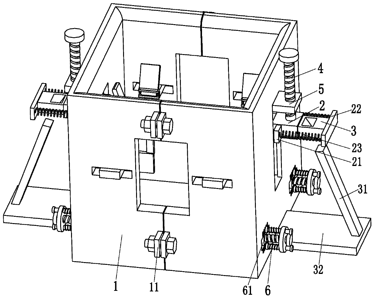
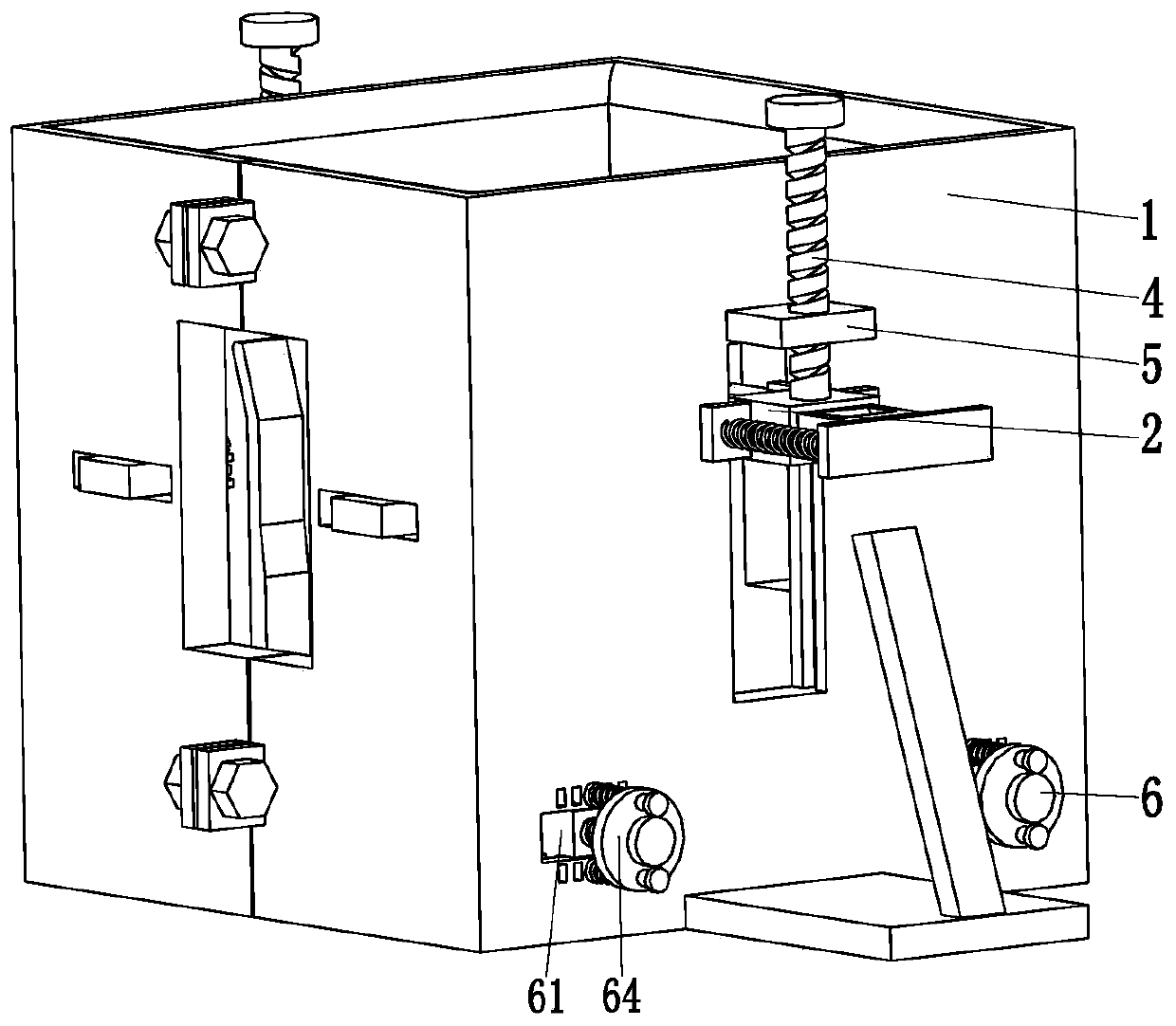
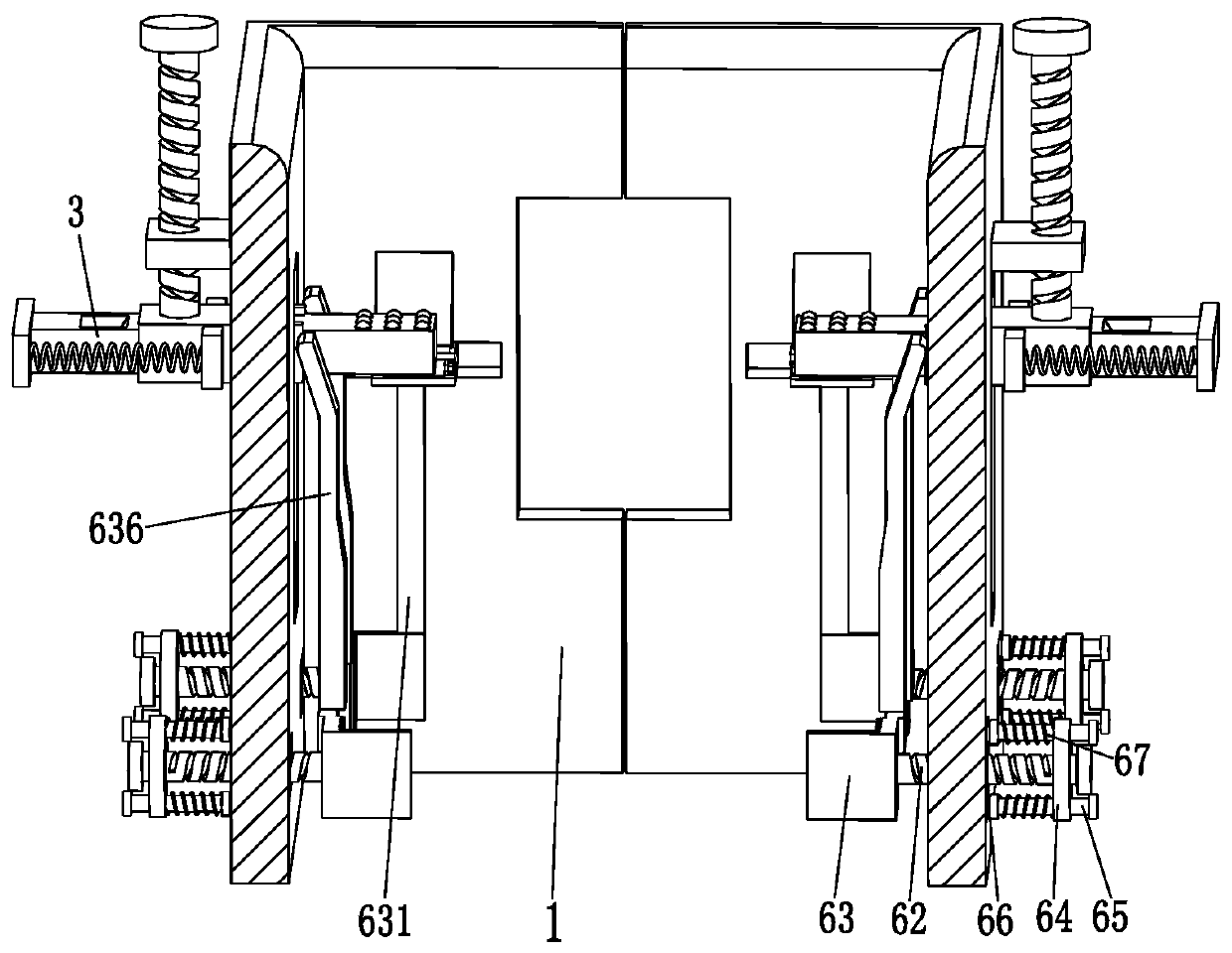
[0029] Such as Figure 1 to Figure 5 As shown, a prefabricated building concrete prefabricated column positioning guide frame includes a guide frame 1, a supporting block 2, a sliding plate 3, a rotating bolt 4, a rotating support plate 5 and a locking mechanism 6, and the guide frame 1 is a square Frame-shaped structure, the left and right sides of the guide frame 1 are longitudinally provided with square grooves, the side walls of the square grooves of the guide frame 1 are provided with slide grooves, and each square groove of the guide frame 1 is fitted with the supporting block ...


PUM


Abstract

The invention relates to an assembled building concrete prefabricated column positioning guiding frame. A guiding frame, bearing blocks, sliding plates, rotation bolts, rotation support plates and locking mechanisms are included. Square grooves are longitudinally formed in the left side face and the right side face of the guiding frame. Each square groove of the guiding frame is connected with thecorresponding bearing block in a sliding fit manner. The tops of the bearing blocks are connected with the lower ends of the rotation bolts through bearings. The middle portions of the rotation boltsare arranged on the rotation support plates in a threaded fit manner. The rotation support plates are connected to the upper end side face of the guiding frame. The corresponding sliding plate penetrates through the middle portion of each bearing block in a sliding fit and inserting manner. The locking mechanisms are symmetrically arranged at the front end and the rear end of the guiding frame. The assembled building concrete prefabricated column positioning guiding frame can solve the problems that the manual prefabricated column straightening effect is poor, manual multi-time alignment is needed, the lower end of a prefabricated column is not supported, the prefabricated column can swing, and consequently the alignment effect of the prefabricated column and a bottom column is poor, wherein the problems exist during inserting and connecting of the prefabricated column and the bottom column at present.

Description

technical field [0001] The invention relates to the technical field of prefabricated buildings, in particular to a positioning guide frame for prefabricated concrete columns of an assembled building. Background technique [0002] In the prefabricated building, each component is produced by prefabrication, and then the various prefabricated parts are transported to the construction site and the prefabricated parts are spliced; the supporting columns in the prefabricated building are basically inserted in the pre-buried On the base column, the bottom is provided with protruding steel bars, and the prefabricated column is provided with sockets at corresponding positions. After the prefabricated column and the base column are aligned, the insertion of the two types of columns can be completed. [0003] When the existing prefabricated columns are plugged on the bottom column, the prefabricated column is generally hoisted to a suitable position by a crane, and the prefabricated co...

Claims


Application Information

Patent Timeline
Patent Type & Authority Patents(China)
IPC IPC(8): E04G21/18
CPCE04G21/1841
Inventor 杜书影胡峰黄勤
Owner TAIAN LIANQIANG YUANDA RESIDENTIAL IND CO LTD
Learn More