Turbofan lamp

A turbofan and fan lamp technology, applied in lampshades, lighting and heating equipment, liquid fuel engines, etc., can solve the problems of low wind power, dim lighting of fan lamps, rapid cooling of meals, etc., to purify the air and improve lighting brightness , beneficial to human health

Inactive Publication Date: 2020-04-21
TORCH LIGHTING
View PDF4 Cites 0 Cited by
  • Summary
  • Abstract
  • Description
  • Claims
  • Application Information

AI Technical Summary

Problems solved by technology

When the user is eating, the blowing surface generated by the fan lamp is mainly concentrated in the dining table area, which is easy to cause rapid cooling of the meal, and at the same time, the people sitting around the dining table can receive less wind
[0004] On the other hand, an axial fan needs to be installed in the middle of the traditional fan light, so light bulbs and other illuminants usually surround the center in a radial shape, which makes the lighting directly under the fan light relatively dark

Method used


Image

  • Turbofan lamp
  • Turbofan lamp

Examples


Embodiment Construction

[0020] The present invention will be further described below in conjunction with specific embodiments and accompanying drawings.

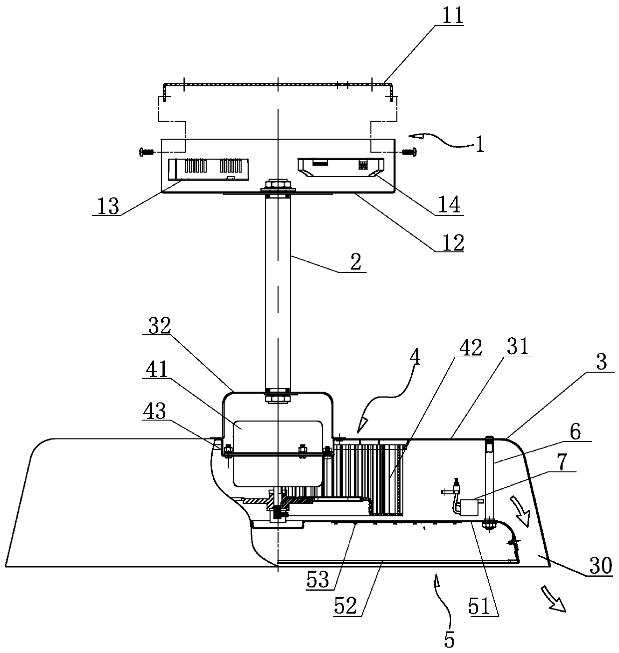
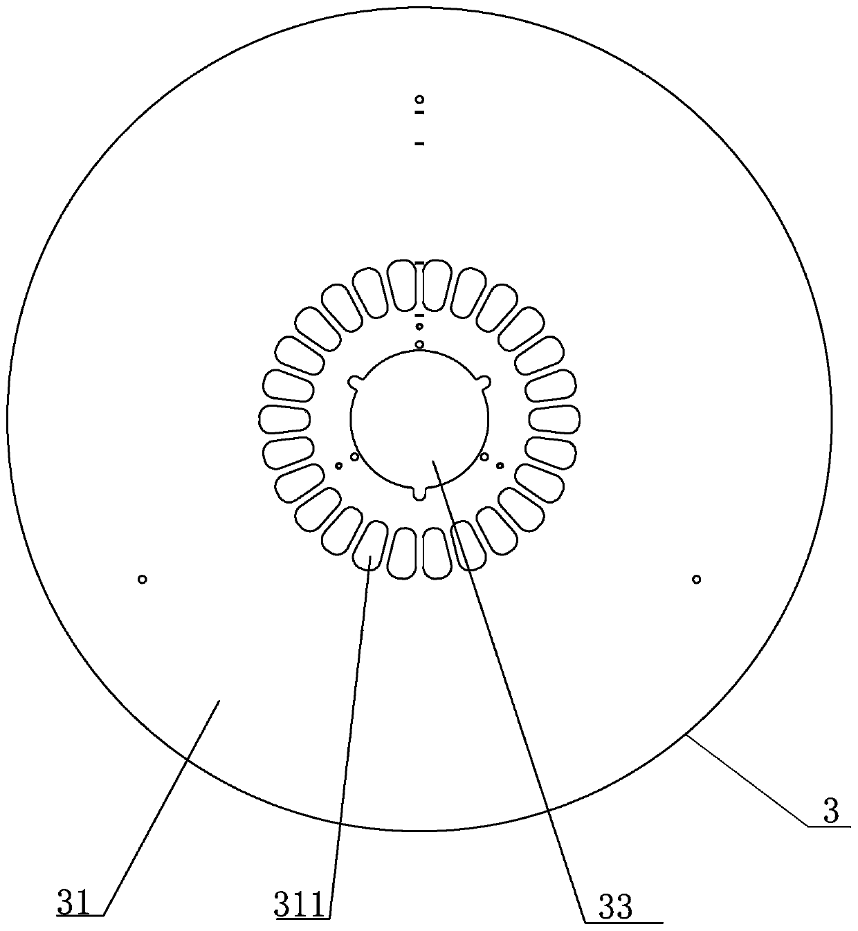
[0021] See figure 1 , figure 2 As shown, the present invention is a turbofan lamp, which includes: a fixed support 1 , a central rod 2 , a lampshade 3 , a fan assembly 4 and a lighting assembly 5 . The fan lamp is fixed on the ceiling through a fixed support 1 , and the lampshade 3 is fixedly connected under the fixed support 1 through a central rod 2 . The fan assembly 4 and the lighting assembly 5 are installed on the lampshade 3 , and the lighting assembly 5 is located below the fan assembly 4 . A gap is formed between the lighting assembly 5 and the inner wall of the lampshade 3, that is, an annular air outlet 30 is formed between the lighting assembly 5 and the inner wall of the lampshade 3, and the airflow generated when the fan assembly 4 works is blown out from the side along the radial direction. The air is blown out from the air outle...


PUM


Abstract

The invention discloses a turbofan lamp, which comprises a fixed support, a center rod, a lampshade, a fan assembly and a lighting assembly, wherein the fan lamp is fixed on the ceiling through the fixed support, and the lampshade is fixedly connected to the lower part of the fixed support through the center rod; the fan assembly and the lighting assembly are installed in the lampshade, and the lighting assembly is located below the fan assembly; an annular air outlet is formed between the lighting assembly and the inner wall of the lampshade, and when the fan assembly works, the airflow generated by the turbine centrifugal fan is blown out from the side surface in the radial direction and blown out downwards from the air outlet along the inner wall of the lampshade. According to the invention, the turbine centrifugal fan is adopted to replace a traditional axial-flow blade fan, the airflow generated by the turbine centrifugal fan is blown out in the radial direction of the turbine centrifugal fan, and the airflow generated by the turbine centrifugal fan is blown out along the annular air outlet, so that an annular air blowing surface can be generated. The central area of the air blowing surface is small in wind power, and the annular area along the periphery of the center is great in wind power.

Description

Technical field: [0001] The invention relates to the technical field of fan lamps, in particular to a turbofan lamp capable of forming an annular blowing surface. Background technique: [0002] Fan light is also called ceiling fan light, which is a product that combines a chandelier with a ceiling fan. The fan lamp not only has the functions of ceiling fan and lighting, but also can be used as an auxiliary appliance of air conditioner to improve the efficiency of air conditioner. [0003] Usually, the lighting lamps and the fan circuit control system in the fan lamp are independent of each other. In order not to affect the lighting, the fan is usually located above and the lighting lamp is located below the fan. At present, the fan blades of the fan part in the fan lamp mostly use 3-5 blades of axial flow fan blades, and the blowing surface is mainly a circular radiation surface located under the fan lamp, which causes a relatively strong wind force under the fan lamp. Thi...

Claims


Application Information

Patent Timeline
Patent Type & Authority Applications(China)
IPC IPC(8): F21V33/00F21S8/06F21V3/02F04D25/08F04D17/16F04D29/42F21Y115/10
CPCF04D17/16F04D25/088F04D29/4226F21S8/06F21V3/02F21V33/0096F21Y2115/10
Inventor 刘瑞志
Owner TORCH LIGHTING
Why Eureka
Try Eureka