
Radio frequency circuit and electronic equipment

A technology of radio frequency circuits and electronic equipment, applied in the field of radio frequency front-end, can solve the problems of large difference loss and poor isolation of radio frequency circuit components, and achieve the effect of less circuit winding, lower cost, and improved signal transmission and reception performance

Active Publication Date: 2020-03-31
VIVO MOBILE COMM CO LTD
View PDF5 Cites 7 Cited by
  • Summary
  • Abstract
  • Description
  • Claims
  • Application Information

AI Technical Summary

Problems solved by technology

[0003] Embodiments of the present invention provide a radio frequency circuit and electronic equipment to solve the problems of large differential loss and poor isolation of radio frequency circuit components currently designed

Method used


Image

  • Radio frequency circuit and electronic equipment
  • Radio frequency circuit and electronic equipment
  • Radio frequency circuit and electronic equipment

Examples


Embodiment Construction

[0020] The following will clearly and completely describe the technical solutions in the embodiments of the present invention with reference to the accompanying drawings in the embodiments of the present invention. Obviously, the described embodiments are some of the embodiments of the present invention, but not all of them. Based on the embodiments of the present invention, all other embodiments obtained by persons of ordinary skill in the art without making creative efforts belong to the protection scope of the present invention.

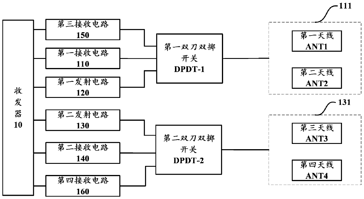
[0021] figure 1 It is a structural schematic diagram of a radio frequency circuit in an embodiment of the present invention. The radio frequency circuit includes a transceiver 10, and a first receiving path, a first transmitting path, a second transmitting path, a second receiving path, a third receiving path and a fourth receiving path respectively connected to the transceiver 10; wherein, as figure 1 Shown:

[0022] The first receiving path in...


PUM


Abstract

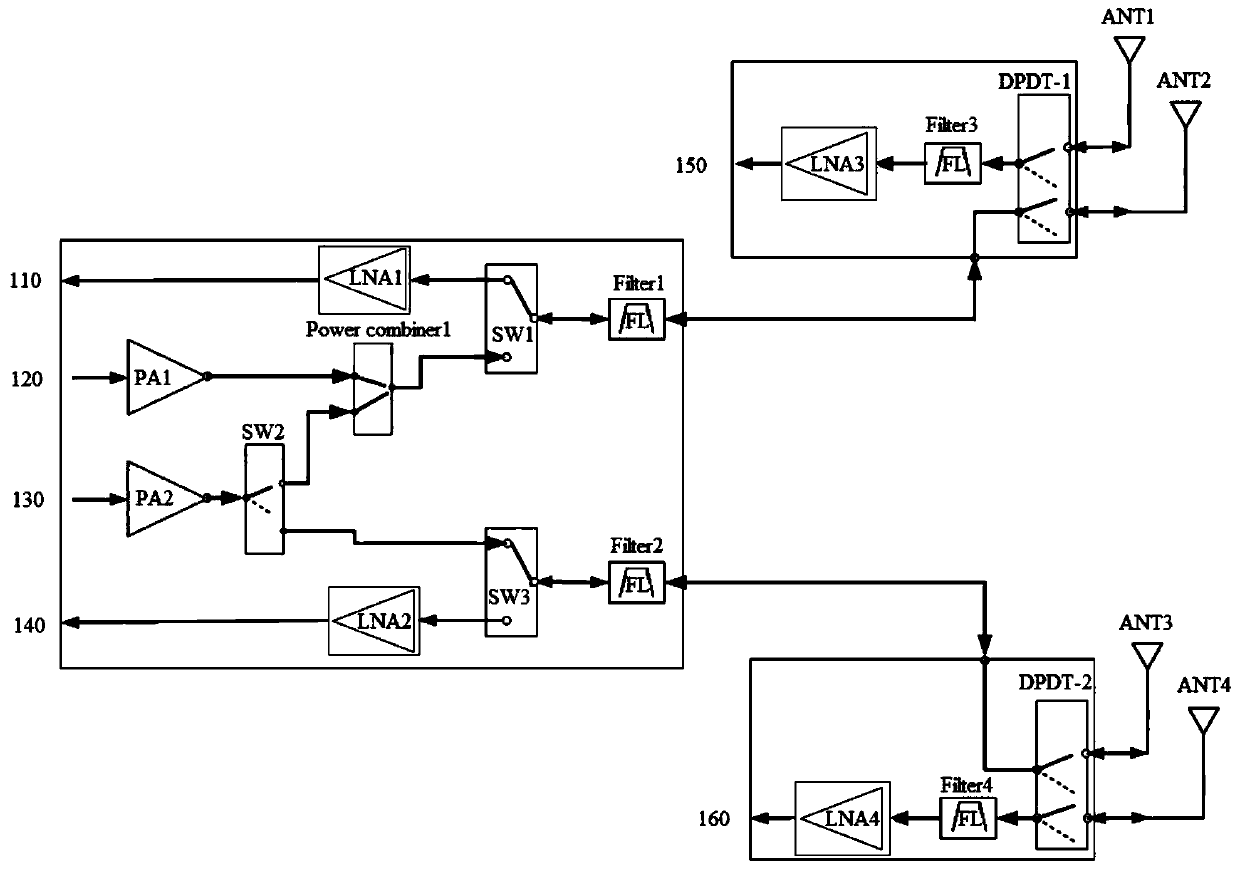
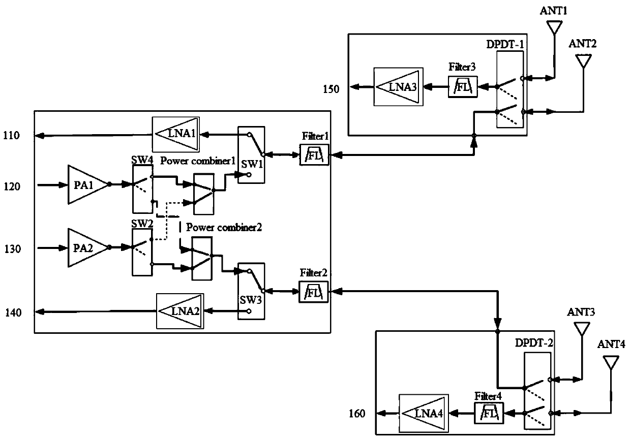
The embodiment of the invention discloses a radio frequency circuit and electronic equipment, and aims to solve the problems of large difference loss and poor isolation of a radio frequency circuit element designed at present. The radio frequency circuit comprises a transceiver, and a first receiving path, a first transmitting path, a second transmitting path, a second receiving path, a third receiving path and a fourth receiving path which are respectively connected with the transceiver. A double-pole double-throw switch is connected with a first antenna group in a first transmitting path, afirst receiving path and a third receiving path, a double-pole double-throw switch is connected with the second antenna group in the second transmitting path, the second receiving path and the fourthreceiving path, and the element difference loss of the double-pole double-throw switch is small, so that the element difference loss caused by using other switches can be effectively reduced by usingthe double-pole double-throw switch in the radio frequency circuit, and the signal receiving and transmitting performance is improved; meanwhile, the switching paths of the double-pole double-throw switch are few, and the isolation degree is better, so that the signal interference can be effectively reduced.

Description

technical field [0001] The invention relates to the field of radio frequency front-end technology, in particular to a radio frequency circuit and electronic equipment. Background technique [0002] With the popularization of mobile smart terminals, users' demand for data traffic continues to increase. From 4G applied to multimedia and broadband, the rate is 100M ~ 1Gbps, and the peak rate of 5GNR (New Radio, new air interface) can reach 20Gbps. The increase in rate requires 5G to have 4*4MIMO (Multiple Input Multiple Output, Multiple Input Multiple Output) technology. At present, the operating frequency required for 5G mobile electronic devices is getting higher and higher, and the bandwidth is getting bigger and bigger, resulting in large component loss and poor isolation. Contents of the invention [0003] Embodiments of the present invention provide a radio frequency circuit and electronic equipment to solve the problems of large dropout and poor isolation of radio fre...

Claims


Application Information

Patent Timeline
IPC IPC(8): H04B1/401H04B7/0413H04B7/06H04B7/08
CPCH04B1/401H04B7/0413H04B7/0602H04B7/0805
Inventor 谢政男文洲
Owner VIVO MOBILE COMM CO LTD
Learn More