In view of the foregoing perceived deficiencies, it is thus one aspect of the present invention to provide a
windmill pumping device which converts
rotational energy to energy to pump a liquid or gas. Thus, in one embodiment of the present invention, a
wind driven pump is provided which utilizes a
piston pump to move fluid or gas into a
storage tank. Preferably the pump is capable of delivering the liquid or gas at a
positive pressure at the point of
discharge. The wide range of leverage available from a downhole
swash plate design provides small amounts of fluid or gas to be moved with low wind velocities, while larger quantities can be pumped at higher wind speeds at the
constant pressure required for each installation.
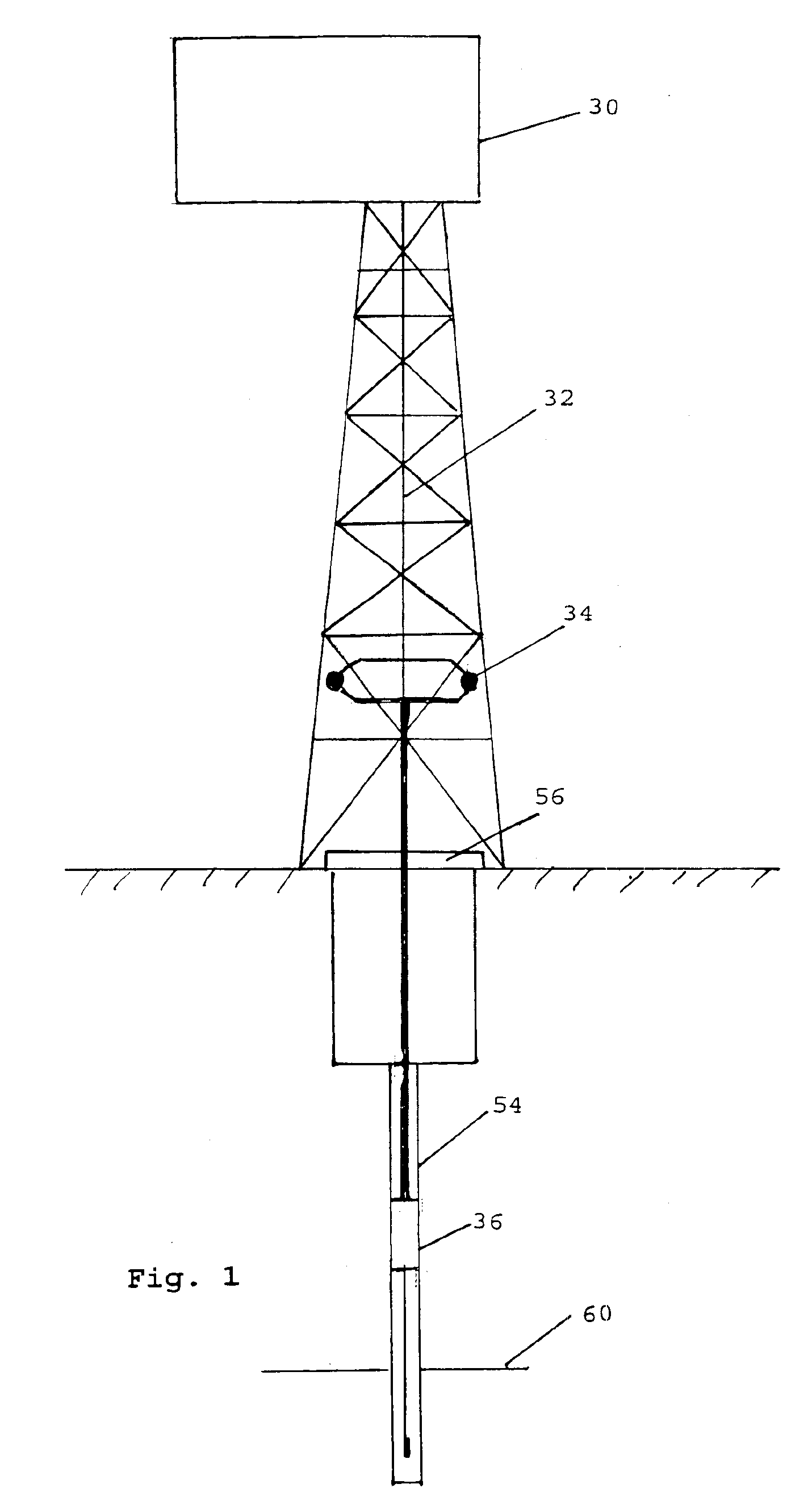
It is a further aspect of the present invention to provide an improved Savonious type wind motor which improves the efficiency of the
windmill, and has a non-traditional
geometric configuration. In a further aspect of the present invention, a wind deflection apparatus is provided in combination with the Savonious type wind motor, and which deflects upstream wind to one side of the Savonious wind motor, while decreasing wind on the other portion of the wind motor, and hence
back pressure. Thus, in one embodiment of the present invention, a substantially triangular shaped wind deflector is provided along with a vertical fin tab which is positioned downstream of the Savonious wind motor.
The Savonious wind rotor also is superior to other wind rotors in that it can efficiently utilize wind gusts which can vary in direction of up to 70 degrees from the prevailing wind without the need to rotate the motor into the direction of the wind. The rotation about the
vertical axis of a motor that is rotating about a
horizontal axis causes stress and strain on the
moving parts within the wind motor and the directional vane that turns the motor into the direction of the wind. This gyroscopic loading condition does not generally occur in the Savonious wind motor. As a further improvement to the present design, a deflector may be provided immediately upstream from the Savonious wind motor to enhance efficiency. The addition of this
enhancer will detract from the efficient utilization of wind gusts but may be added if the maximum utilization of available power from low wind velocities is required. In one embodiment of the present invention, a
brake is located just below the wind motor which is activated from within the well house. This
brake will stop all power input to allow for maintenance and inspection of the various components of the present invention.
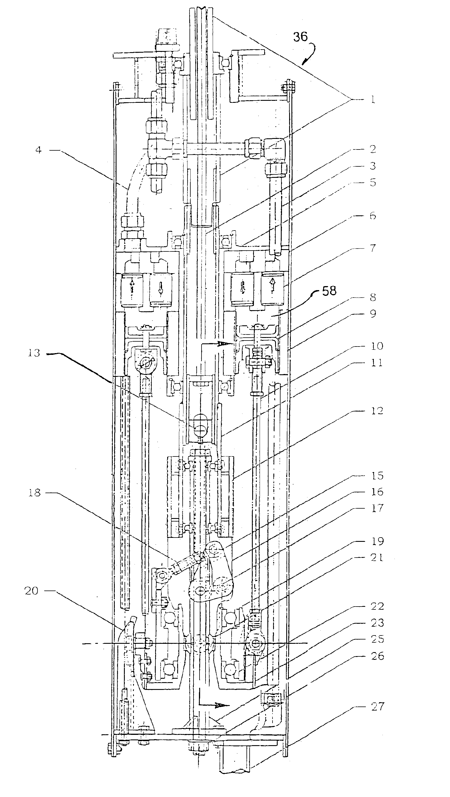
It is a further aspect of the present invention to provide a non-rotating
swash plate type design to convert
rotational energy to reciprocating vertical energy to move one or more pistons. Thus, a unique feature of the present
pump design is that the
swash plate does not rotate but simply wobbles about a center
spherical bearing. This feature presents an
advantage in that it eliminates the friction and wear between the
piston push rods and a rotating swash plate. The “swashing” action is achieved through a driving yoke which rotates a swash drive around the bearing pedestal of the swash plate. These two parts are held together by two sealed ball bearings which allow only rotational movement between the two. The pistons are attached to and activated by push rods which have Teflon lined rod ends. This design feature also cuts down the wear and friction assuring a maintenance free, long life pump.
As the wind velocity increases, the
governor tilt
control rod, which is attached on the lower end to the swash plate tilt mechanism increases the
angle of inclination of the swash plate, thus lengthening the
stroke of the pistons and increasing the volume of substance pumped. As the wind velocity decreases, the
governor alters the position of the tilt
control rod, which subsequently lowers the inclination of the swash plate and thus the
stroke of the pistons. As the windmill and the interconnected rotating device shaft stop rotating, the
governor returns to its position of no tension on the tilt
control rod and the swash plate pump drive is positioned substantially perpendicular to the driving shaft and the pump is oriented to its neutral, or no pumping position. Stating this mathematically, “as the swash plate
angle of inclination approaches zero, the
mechanical advantage approaches infinity”. This feature assures that the system will not stall in a position that the Savonious wind motor cannot drive even under wind velocities of three to five
miles per hour, since the
stroke length on the pistons is reduced proportionately as the
wind speed declines.

