Lens distortion compensation method and device, and storage medium
A technology of lens distortion and compensation method, which is applied in TV, color TV parts, electrical components, etc., can solve the problems of resource loss, multiple human resources and time resources, etc.
- Summary
- Abstract
- Description
- Claims
- Application Information
AI Technical Summary
Problems solved by technology
Method used
Image
Examples
Embodiment 1
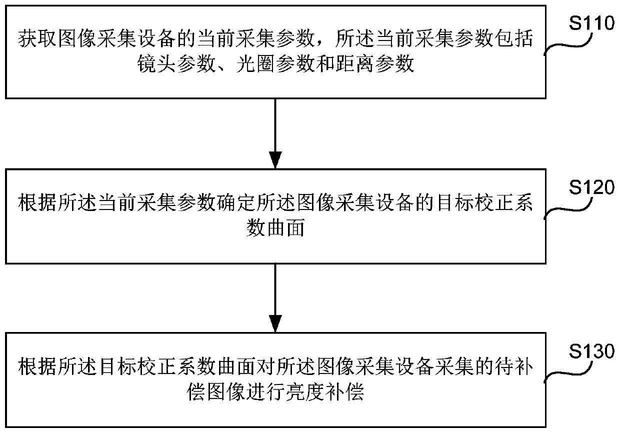
[0030] Embodiment 1 of the present invention provides a lens distortion compensation method. The method can be performed by a lens distortion compensation device, wherein the device can be implemented by software and / or hardware, and generally can be integrated in an image acquisition device (such as a camera, a camera, etc.), and is suitable for when the acquisition parameters of the image acquisition device change , re-determine the correction coefficient of the image acquisition device and perform distortion compensation on the image acquisition device based on the correction coefficient. figure 1 is a schematic flow chart of the lens distortion compensation method provided in Embodiment 1 of the present invention, as shown in figure 1 As shown, the method includes:
[0031] S110. Acquire current acquisition parameters of the image acquisition device, where the current acquisition parameters include lens parameters, aperture parameters, and distance parameters.
[0032] I...
Embodiment 2
[0045] Figure 4 It is a schematic flowchart of lens distortion compensation provided by Embodiment 2 of the present invention. In this embodiment, on the basis of the above-mentioned embodiments, the optimization of "determining the target correction coefficient surface of the image acquisition device according to the current acquisition parameters" is as follows: determining the current parameter class to which the current acquisition parameters belong; A correction coefficient surface corresponding to the current parameter class is obtained as a target correction coefficient surface of the image acquisition device.
[0046] Further, before the acquisition of the current acquisition parameters of the image acquisition device, it also includes: performing image acquisition under different acquisition parameters, so as to determine the brightness distortion surface corresponding to each acquisition parameter according to the acquired image; according to the brightness distorti...
Embodiment 3
[0062]Embodiment 3 of the present invention provides a lens distortion compensation device. The device can be implemented by software and / or hardware, and generally can be integrated in an image acquisition device (such as a camera, a camera, etc.), and is suitable for re-determining the correction coefficient of the image acquisition device and based on The correction coefficient performs distortion compensation on the image acquisition device. Image 6 The structural block diagram of the lens distortion compensation device provided for Embodiment 3 of the present invention, as shown in Image 6 As shown, the lens distortion compensation device includes a parameter acquisition module 301, a coefficient determination module 302 and a brightness compensation module 303, wherein,
[0063] A parameter acquisition module 301, configured to acquire current acquisition parameters of the image acquisition device, where the current acquisition parameters include lens parameters, aper...
PUM
 Abstract
Description
Claims
Application Information
 - R&D
- Intellectual Property
- Life Sciences
- Materials
- Tech Scout
- Unparalleled Data Quality
- Higher Quality Content
- 60% Fewer Hallucinations
Browse by: Latest US Patents, China's latest patents, Technical Efficacy Thesaurus, Application Domain, Technology Topic, Popular Technical Reports.
© 2025 PatSnap. All rights reserved.Legal|Privacy policy|Modern Slavery Act Transparency Statement|Sitemap|About US| Contact US: help@patsnap.com


