Gear string key mechanical anti-theft lock

A technology of mechanical anti-theft locks and gears, applied in keys, building locks, buildings, etc., can solve the problems of high processing precision and high manufacturing cost

Active Publication Date: 2020-04-24
BEIHUA UNIV
View PDF16 Cites 10 Cited by
  • Summary
  • Abstract
  • Description
  • Claims
  • Application Information

AI Technical Summary

Problems solved by technology

[0006] Along with technology development, a number of patented products with "lock cylinder fixed cross mechanical anti-theft lock" as the core technology in the later period, including "lock cylinder fixed cross mechanical anti-theft lock matching fingerprint lock" (ZL201610990489.0), "a Cam Mechanism for Fingerprint Lock" (ZL201611045195.7), "Double Plug-in Anti-theft Door and External Locking Device" (ZL201610129609.8), "A Forced Reset Device for Rotating Ring of Anti-theft Lock" (ZL201710390280.5), " Cam Mechanism of Fingerprint Lock and Forced Reset Device of Rotating Ring" (ZL201710435512.4), "Automatic Reset and Idling Device of Stop Handle" (ZL201710393215.8), "Single Clutch Cam Mechanism of Fingerprint Lock" (ZL201810363492.9) , "Press-down assembly tool for anti-theft lock cam...

Method used


Image

  • Gear string key mechanical anti-theft lock
  • Gear string key mechanical anti-theft lock
  • Gear string key mechanical anti-theft lock

Examples


Embodiment approach 1

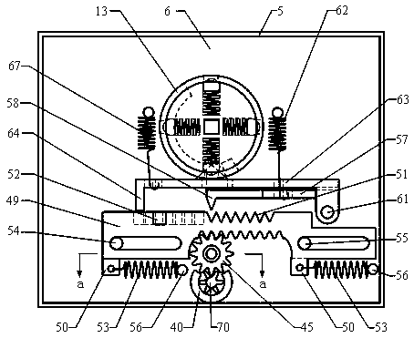
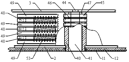
[0071] Such as figure 1 , 31 , 39, a lock body 1 of a gear chain key mechanical anti-theft lock includes an outer panel 2, a partition 3, an inner panel 4 and a surrounding panel 5, and the rectangular cavity between the outer panel 2 and the partition 3 is the outer cavity Body 6, the rectangular cavity between the partition plate 3 and the inner side plate 4 is the inner cavity body 7, the side of the outer side plate 2 that is located outside the lock body 1 is the outer side 8 of the lock body, and the side of the inner side plate 4 that is located outside the lock body 1 The side is the inner side 9 of the lock, and the inner side of the door outer panel 11 is provided with a reinforcing plate 12, the lock body 1 is fixedly mounted on the reinforcing plate 12, and the outer side 8 of the lock is in contact with the reinforcing plate 12. The outside of the door leaf outer panel 11 is provided with a lock outer panel 68, and the handle rotating shaft 10 and the forward an...

Embodiment approach 2

[0107] Such as Figure 40 , 41 As shown, the positions of the various parts of the unlocking control mechanism can also be rearranged, that is, the unlocking control mechanism of Embodiment 1 is turned forward or backward at an angle of 180 degrees. Above, the center of the keyhole 41 is still on the same vertical line as the center of the cam mechanism, the rectangular long hole 43 is located at the bottom of the circular tube 40, the gear shaft 44 and the intermediate gear 45 are located directly below the circular tube 40, and the rack is located at the center of the intermediate gear 45. Below, the locking plate 57 and the unlocking plate 63 are located between the rack and the cam 13, wherein the unlocking plate 63 is located under the locking plate 57 and above the cam 13. The bars respectively move corresponding distances from left to right, and then press down the handle, the cam mechanism rotates forward, the first flange 15 of the cam 13 first pushes the clamping ba...


PUM


Abstract

The invention discloses a gear string key mechanical anti-theft lock, and relates to the field of mechanical anti-theft locks. A key hole and a handle rotating shaft are arranged on a same vertical line; a key is formed by connecting a plurality of small gears in series; each small gear is a complete gear, or an incomplete gear, or a gear with no tooth; and the key drives all racks to run for different distances through an intermediate gear. After the key is rotated for one circle, the handle drives a cam to firstly push a locking plate to be inserted into saw teeth of the racks, then the racks cannot move any more, the cam pushes an unlocking inserting plate to be inserted into rectangular openings of the racks, and the cam can continuing rotating for unlocking. When the key is incorrect,the locking plate can still clamp the racks firstly and the racks cannot move, but the unlocking inserting plates cannot be inserted into the rectangular openings, so that the cam is prevented from rotating, and the lock cannot be unlocked. If the handle is twisted strongly, the handle is idle. Locking can be completed without using a key but reversely lifting the handle. The racks, the intermediate gear and the like are simple in structure, can be stamped and processed, and are low in manufacturing cost. The lock has the characteristics of preventing technical unlocking, preventing unlockingby damage, large key amount, stability, durability and the like.

Description

technical field [0001] The invention relates to the field of mechanical anti-theft locks, in particular to a gear chain key mechanical anti-theft lock. Background technique [0002] At present, common mechanical anti-theft locks in the prior art mainly include tumbler locks, blade locks and hybrid anti-theft locks of the two. Among them, according to the structure of the tumbler lock, the shape of the key can be divided into ordinary single-sided tooth pattern (commonly known as a word lock), double-sided tooth pattern, cross-shaped tooth pattern, single-row or double-row round pits, etc.; the key corresponding to the leaf lock There are one or two serpentine curved grooves on the top; the key of the hybrid anti-theft lock has both serpentine curved grooves and pits. [0003] The main performance of the mechanical anti-theft lock is reflected in the following five aspects: 1. Anti-technical opening performance; 2. Anti-destructive performance, including anti-drilling functi...

Claims


Application Information

Patent Timeline
IPC IPC(8): E05B19/06E05B19/08E05B15/00E05B15/14E05B17/20
CPCE05B15/00E05B15/143E05B17/2084E05B19/0017E05B19/0035
Inventor 吕雪寒
Owner BEIHUA UNIV
Why Eureka
Try Eureka