
High-speed bearing retainer with reinforcing ribs

A technology for high-speed bearings and cages, which is applied to bearing components, shafts and bearings, mechanical equipment, etc., and can solve problems such as cage wear, high speed requirements, and damage

Inactive Publication Date: 2020-04-24
CIXING GROUP
View PDF9 Cites 0 Cited by
  • Summary
  • Abstract
  • Description
  • Claims
  • Application Information

AI Technical Summary

Problems solved by technology

[0002] The electric vehicle drive system has high requirements on the speed of the bearing, which is 2-3 times the theoretical limit speed of the traditional bearing. The cage of the original high-speed bearing rubs against the outer ring due to centrifugal force during high-speed rotation, causing wear and tear on the cage. damage
Therefore, the original traditional bearings cannot meet the requirements

Method used

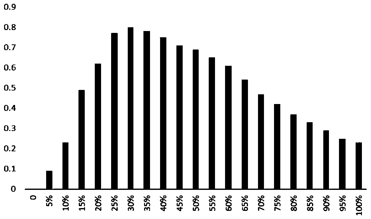

Image

  • High-speed bearing retainer with reinforcing ribs
  • High-speed bearing retainer with reinforcing ribs
  • High-speed bearing retainer with reinforcing ribs

Examples


Embodiment Construction

[0013] The present invention will be further described below in conjunction with the accompanying drawings and specific embodiments.

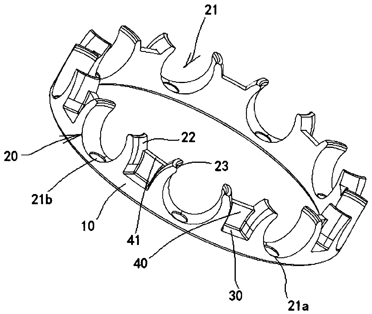
[0014] see figure 1 , a height bearing cage with reinforcing ribs shown in the figure includes a ring frame body 10, and a number of cage ball pockets 20 are arranged at intervals on one end surface of the ring frame body 10, and each cage ball pocket 20 is provided with a ball pocket hole 21 .

[0015] The present invention is characterized in that: a reinforcing rib 40 is arranged on the cage shoulder 30 between two adjacent ball pockets 20, the reinforcing rib 40 is arranged on the inner side of the cage shoulder 30, and the two sides of the reinforcing rib 40 are respectively connected with The catch outer spherical surfaces 22 of two adjacent cage ball pockets 20 are connected as a whole, the upper plane 41 of the reinforcing rib 40 is lower than the upper surface 23 of the cage ball pocket 20, and the thickness of the reinforcing rib 40 ...


PUM


Abstract

The invention discloses a high-speed bearing retainer with reinforcing ribs. The high-speed bearing retainer comprises an annular frame body, wherein a plurality of retainer ball pockets are arrangedon one end face of the annular frame body at intervals, and a pocket hole is formed in each retainer ball pocket; and the high-speed bearing retainer is characterized in that reinforcing ribs are arranged on the retainer shoulders between two adjacent retainer ball pockets, and the two sides of the reinforcing ribs are integrally connected with the pocket grasping outer spherical surfaces of two adjacent retainer ball pockets correspondingly. The bearing retainer is applied to a high-speed bearing, and the running speed of the bearing can be ensured to meet the requirement.

Description

technical field [0001] The invention relates to the technical field of bearings, in particular to a high-speed bearing cage with reinforcing ribs. Background technique [0002] The electric vehicle drive system has high requirements on the speed of the bearing, which is 2-3 times the theoretical limit speed of the traditional bearing. The cage of the original high-speed bearing rubs against the outer ring due to centrifugal force during high-speed rotation, causing wear and tear on the cage. damage. Therefore, the original traditional bearings cannot meet the requirements. Contents of the invention [0003] The technical problem to be solved by the present invention is to provide a high-speed bearing cage with ribs for the above-mentioned shortcomings in the application of the existing high-speed bearings in the drive system of electric vehicles, which can ensure the running speed of the bearings when used in high-speed bearings fulfil requirements. [0004] The technic...

Claims


Application Information

Patent Timeline
Patent Type & Authority Applications(China)
IPC IPC(8): F16C33/38
CPCF16C33/3812F16C33/3856
Inventor 赵坤胡武沈光飞
Owner CIXING GROUP
Learn More