
Traveling crane positioning system and positioning method

A positioning system, crane technology, applied in the direction of load hanging components, transportation and packaging, to achieve the effect of improving work efficiency

Inactive Publication Date: 2009-12-09
TIANJIN UNIVERSITY OF TECHNOLOGY
View PDF9 Cites 3 Cited by
  • Summary
  • Abstract
  • Description
  • Claims
  • Application Information

AI Technical Summary

Problems solved by technology

[0003] The purpose of the present invention is to solve the above-mentioned many problems existing in the existing crane positioning, improve the positioning accuracy and production efficiency of the crane, provide a high-precision crane positioning system, and provide a convenient and intuitive monitoring interface for the crane operators

Method used


Image

  • Traveling crane positioning system and positioning method
  • Traveling crane positioning system and positioning method
  • Traveling crane positioning system and positioning method

Examples


Embodiment 1

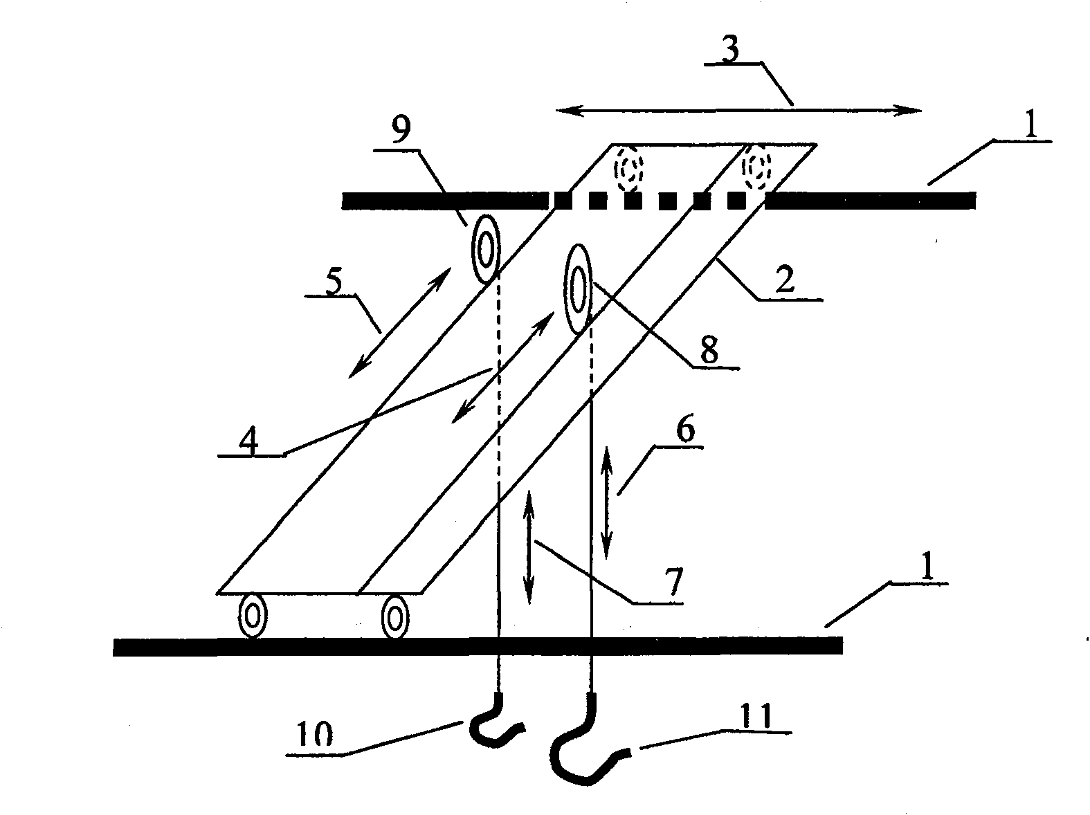
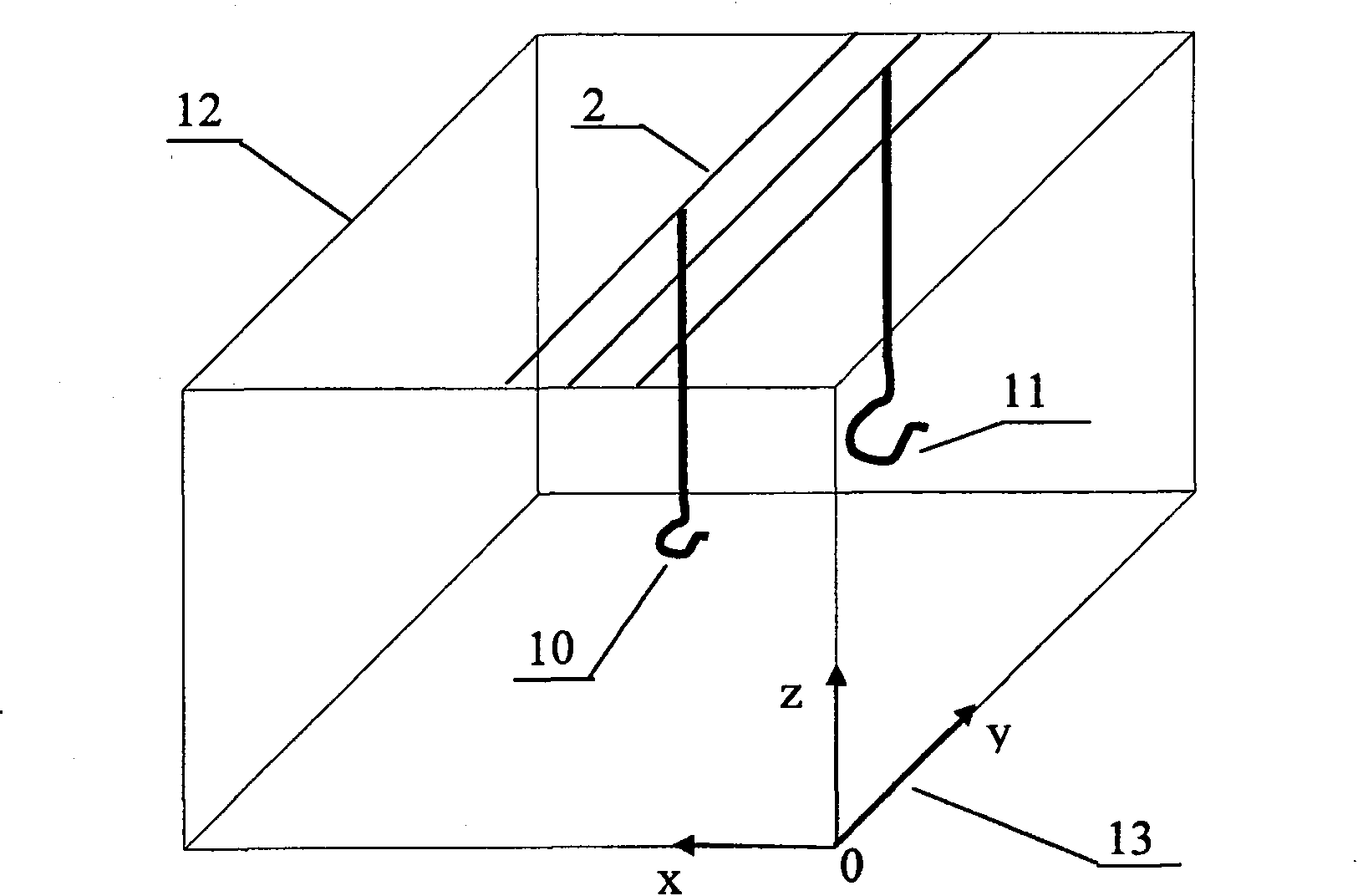
[0040] exist figure 1 In , the layout diagram of the location of the crane is given. From figure 1 It can be seen that the crane is composed of a cart, main and auxiliary trolleys, main and auxiliary hooks, etc. If the crane wants to lift a heavy object, it should first drive the cart to run directly above the position of the heavy object, and then adjust the main and auxiliary hooks. The trolley is positioned so that the hook is directly above the heavy object, and finally the height of the main hook is adjusted to lift the heavy object. From this process, the coordinates of the positioning of the crane can be obtained, that is, the running direction of the large crane is x, the running direction of the main trolley and auxiliary trolley of the crane is y, and the running direction of the main and auxiliary hooks is set to z. Through this coordinate, the location of the transferred goods can be precisely located.

[0041] figure 2 The coordinate system setting position d...


PUM


Abstract

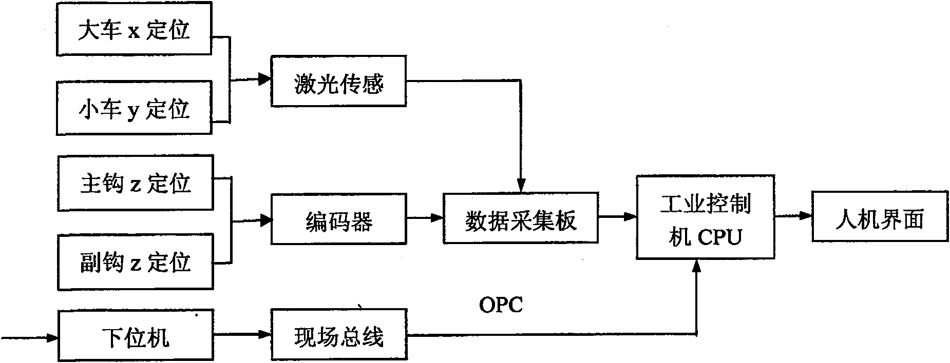
A crane positioning system and positioning method. The invention adopts the industrial control computer as the core, organically integrates the industrial control computer, the data acquisition card, the lower computer PLC and the sensor, and fully exerts their respective advantages. On the basis of not affecting the design and control scheme of the original crane, the system uses high-precision laser sensors and encoders to measure the distances of the crane in the three directions of x, y, and z, and sends them to the industrial control through different types of data acquisition cards. In the computer CPU, at the same time, OPC technology is used to read the running status of the crane from the lower computer PLC to the upper computer-industrial control computer in real time through the field bus, and then use Visual Basic and other advanced languages ​​to write data processing and interface in the industrial control computer. The display program achieves the purpose of displaying the running position and status of the crane in real time, thereby providing the crane operator with accurate data on the operation of the crane, and at the same time providing a solid research foundation for the realization of high-precision unmanned driving of the crane.

Description

technical field [0001] The invention relates to a high-precision crane positioning system and positioning method. Background technique [0002] There are two traditional ways to locate the crane. One is to draw colored bars of different colors on a wall in the direction of the crane’s running. Each color represents a certain distance. The driver of the crane should check the colored bars on the wall at any time. , and then to judge the position of the crane, the distance between every two color bars is at least 20cm, so that the positioning of the crane is inaccurate, and at the same time, the operator of the crane is required to have a good memory and Only by experience can we know the approximate location of the crane. At the same time, there must be a person under the car to direct, so that the crane can reach the predetermined position, and the efficiency is extremely low. This method has relatively high requirements for the crane operator, who must be a very experienc...

Claims


Application Information

Patent Timeline
Patent Type & Authority Patents(China)
IPC IPC(8): B66C13/16
Inventor 冷建伟杜明星姚晓伟屈重年马中原
Owner TIANJIN UNIVERSITY OF TECHNOLOGY
Learn More